Diverter Valve with Minimum Bias Forces

a diverter valve and bias force technology, which is applied in the direction of water installation, flushing devices, construction, etc., can solve the problems of waste of water, difficulty in refilling the bowl after a flush, and equally empty bowls, etc., and achieves the effect of simple and compact operation, minimal effort, and minimal components

Inactive Publication Date: 2010-02-25
FLUIDMASTER
View PDF6 Cites 5 Cited by
  • Summary
  • Abstract
  • Description
  • Claims
  • Application Information

AI Technical Summary

Benefits of technology

[0012]A first advantage of the present diverter valve is that it is simple and compact, and operates very easily with minimal components.
[0013]A second advantage of the present diverter valve is that the slidable poppet may be moved between its raised and lowered positions with only a minimum amount of effort. Specifically, in one embodiment, the unique saucer-shaped dimensions of the poppet ensure that only minimum forces are required to lift it to its raised position or to drop it to its lowered position. As a result, the present diverter valve directs fluid from an inlet valve to one of two outlets with only minimum activated or bias force being required.
[0014]For example, in one preferred aspect, the top conical shape of the poppet provides lift as water passes thereover. Thus, when the poppet is slightly raised (i.e.: positioned slightly away from sealing the entrance to the second outlet), the upward force from the water flow passing thereover can assist in pulling the poppet upward with minimal effort required. Only a small external force is thus required to overcome the weight of the poppet and keep it in its raised position. If this small external force is removed, the weight of the poppet (along with another small external force) will disengage the poppet from its raised position, and move it downward.
[0015]The preferred unique geometry of the poppet (i.e.: having upper and lower saucer-shaped conical surfaces) causes the water pressure exerted on both sides of the poppet to be almost equal (when the poppet is disposed mid-way between its raised and lowered positions). Thus, only minimal effort is required to slidably move the poppet in either direction. As a result, movement of a small buoyant weight cup in the tank can be used to activate the activation lever. As only minimal forces are required to activate the diverter valve, this buoyant weight cup can be relatively small, and fit within the frame of a tower flush valve.
[0016]In addition, the uniquely shaped upper and lower surfaces of the poppet cleanly seal against the first and second outlet ports, respectively. Water back pressure in the valve chamber can also assist in holding the poppet in its lowered position (sealing the mouth of the second outlet port).

Problems solved by technology

However, the different flush sizes in a dual flush toilet creates difficulties for refilling the bowl after a flush.
However, the bowl is equally empty after both partial flushes and full flushes.
The problem that thus arises is that bowl must be refilled to the same level after both partial flushes and full flushes, even though the refill valve is open for different durations of times depending on the flush that just occurred.
If the water level in the bowl is too low, it may not block sewage gasses from entering the room from the sewer.
If the water level in the bowl is too high, then water is wasted.
Since the main purpose of dual flush toilets is to conserve water, simply calibrating the toilet to fill to the correct level after a partial flush is not a satisfactory solution because then the bowl would be overfilled after a full flush (since the refill valve is open longer after a full flush).
Similarly, simply calibrating the toilet to fill to the correct level after a full flush is not a solution because then the bowl would be underfilled after a partial flush (since the refill valve is open less time after a partial flush), potentially allowing sewage gasses into the room.

Method used


Image

  • Diverter Valve with Minimum Bias Forces
  • Diverter Valve with Minimum Bias Forces
  • Diverter Valve with Minimum Bias Forces

Examples


Embodiment Construction

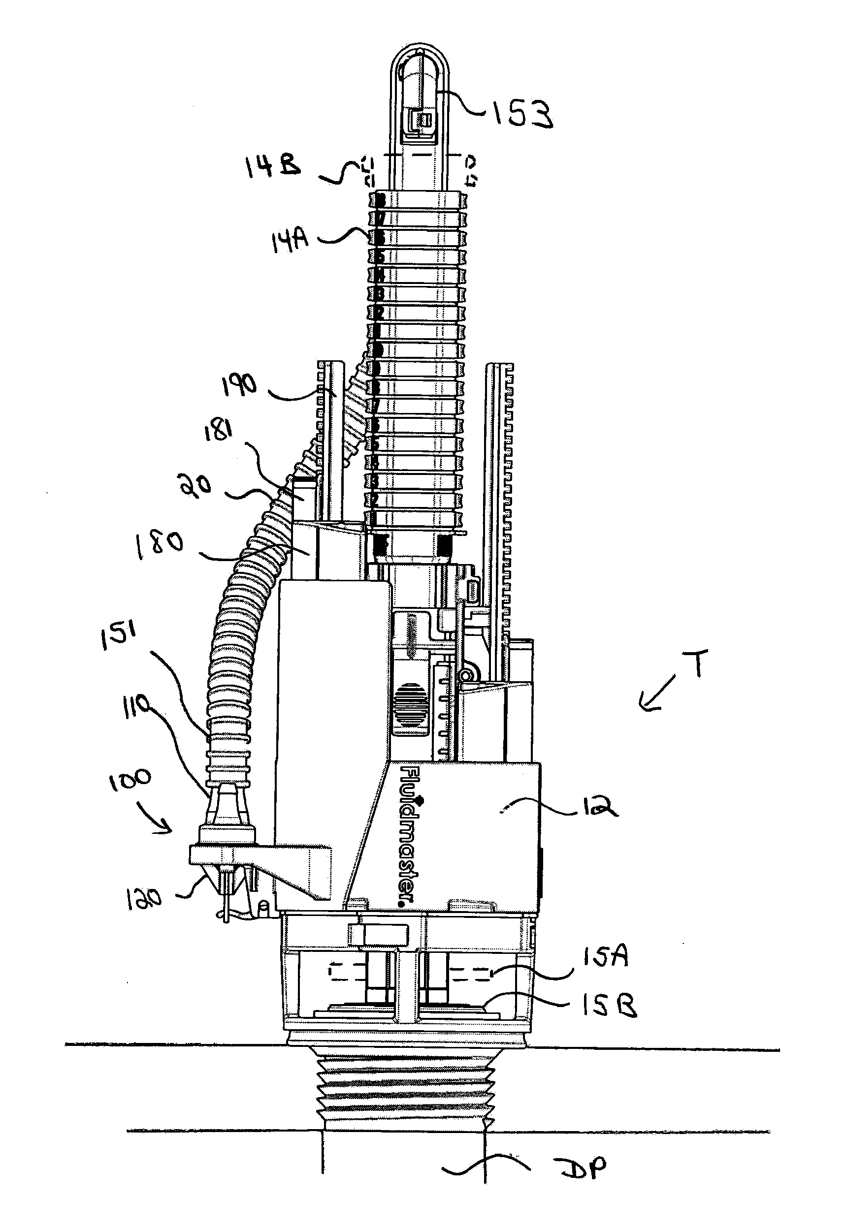
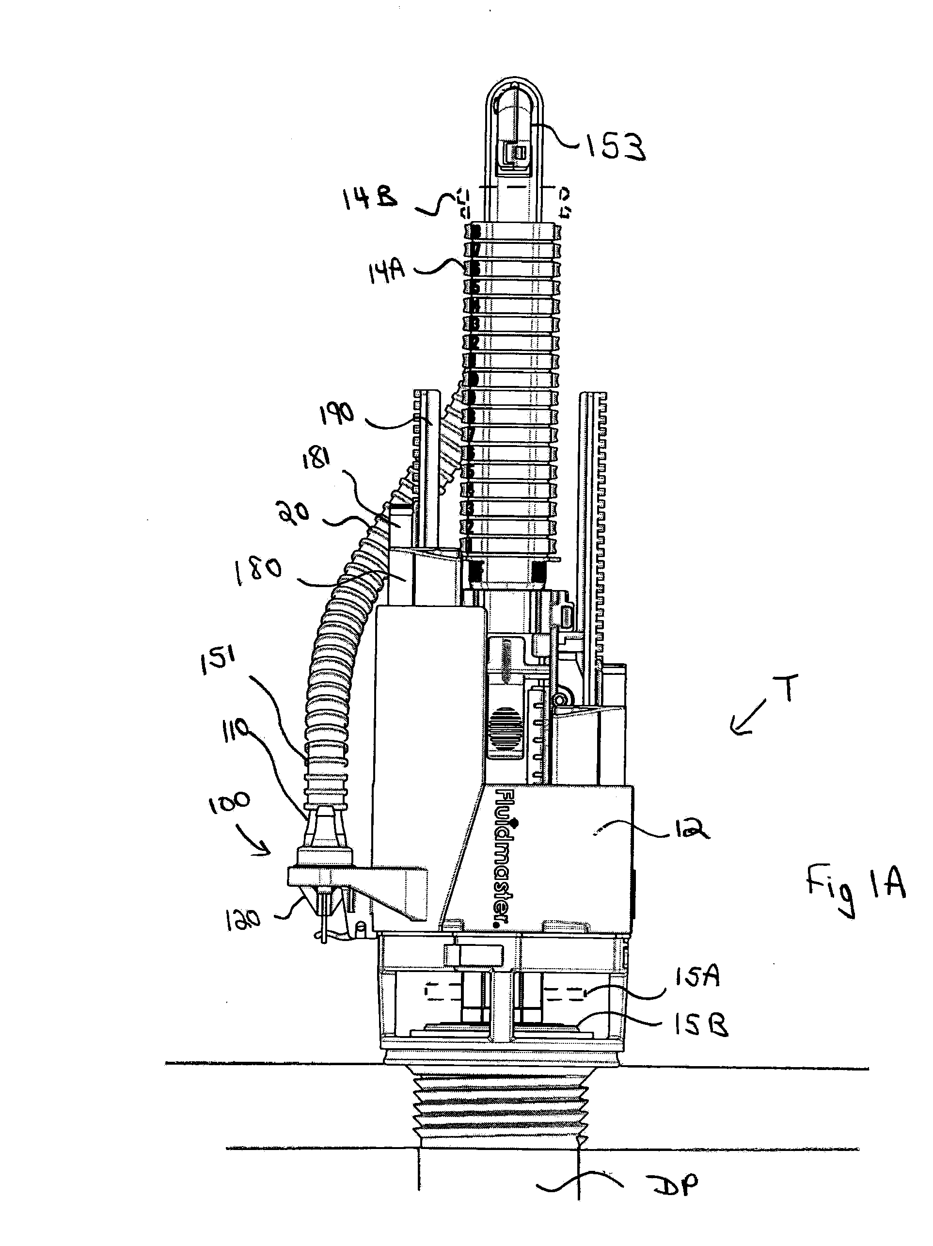
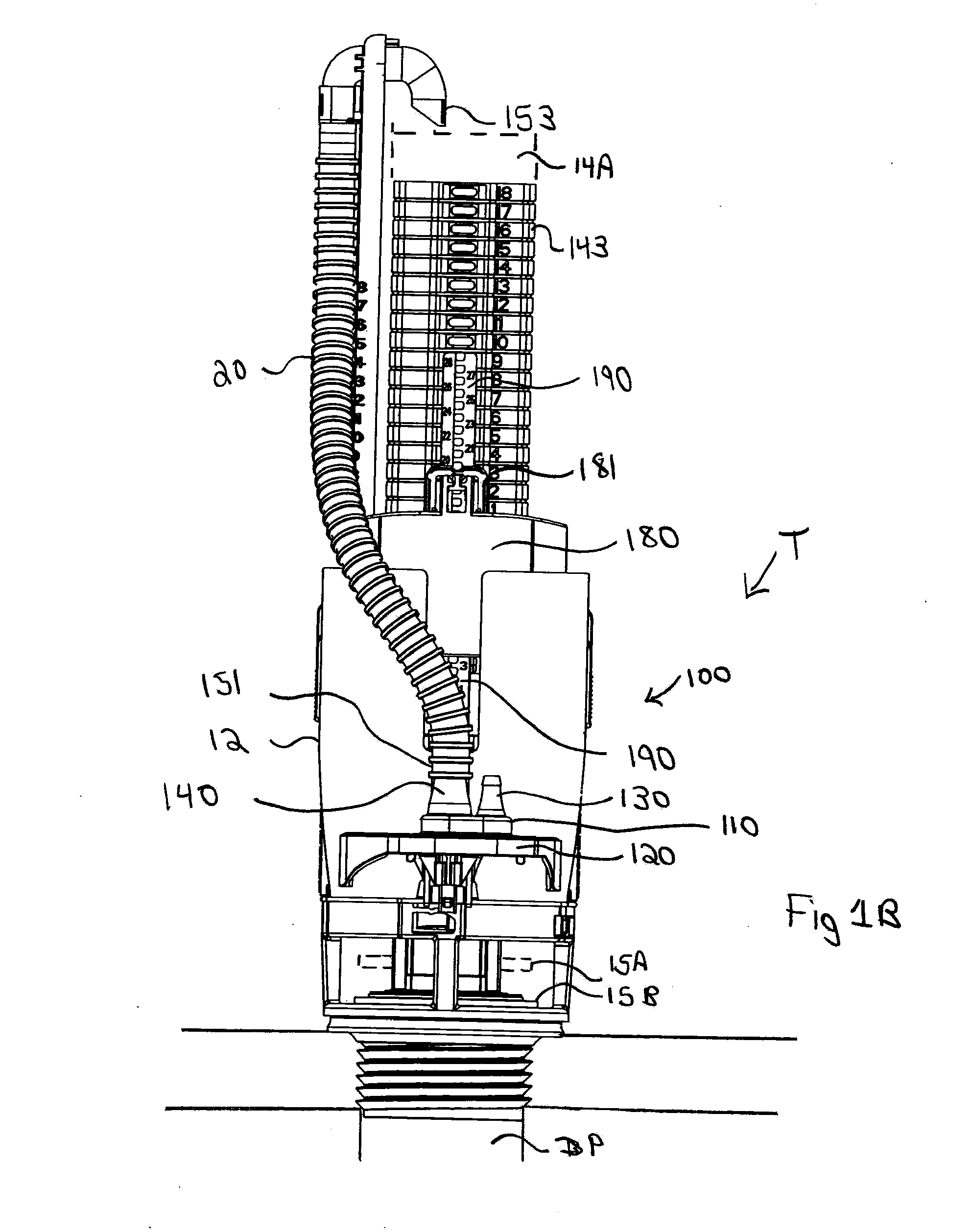
[0026]Exemplary embodiments of the invention are described in detail below with reference to the appended figures, wherein like elements are referenced with like numerals throughout. The figures are not necessarily drawn to scale and do not necessarily show every detail or structure of the various embodiments of the invention, but rather illustrate exemplary embodiments and mechanical features in order to provide an enabling description of such embodiments.

[0027]Various modifications and alterations of the invention will become apparent to those skilled in the art without departing from the spirit and scope of the invention, which is defined by the accompanying claims. For example, it should be noted that steps recited in any method claims below do not necessarily need to be performed in the order they are recited. For example, in certain embodiments, steps may be performed simultaneously. The accompanying claims should be constructed with these principles in mind.

[0028]Any element ...


PUM


Abstract

A diverter valve including: an inlet port coupled to a refill tube; a first outlet port; a bowl refill tube coupled to the outlet port with its second end adjacent to a toilet tank overflow tube; a second outlet port; a central flow passageway providing a path of fluid communication between the inlet port and the first and second outlet ports, the entrance of the first outlet port and the entrance of the second outlet port being directly opposite one another in the central flow passageway; a poppet in the central flow passageway, the poppet having a raised position obstructing the first outlet port and a lowered position obstructing the second outlet port; an actuating arm, float member and rod coupled to the poppet, wherein movement of the float member translates downward motion of the rod into upward motion of the actuating arm and vice versa.

Description

CROSS-REFERENCE TO RELATED APPLICATIONS[0001]The present application claims priority to provisional patent application Ser. No. 61 / 087,929 filed Aug. 11, 2008, entitled “Diverter Valve With Minimum Bias Forces,” which is incorporated by reference into the instant application as if set forth verbatim.FIELD OF THE INVENTION[0002]The present invention relates generally to toilet tank refill valves, and in one aspect to a toilet tank refill valve for a dual flush toilet.BACKGROUND OF THE INVENTION[0003]Conventional toilets generally have a flush valve that is manually actuated by a user, which when opened causes a predetermined amount of water to flow from toilet tank into the toilet bowl, thereby initiating a flush of the toilet bowl. In conventional toilets, the size of the flush (i.e. the volume of water that flows into the bowl from the tank) is constant. The tank includes a refill valve which is used to refill both the toilet tank and the toilet bowl after the flush. The refill val...

Claims


Application Information

Patent Timeline
Patent Type & Authority Applications(United States)
IPC IPC(8): E03D1/00
CPCE03D1/35
Inventor LE, TUANCOLLIN, ROBERT
Owner FLUIDMASTER
Why Eureka
Try Eureka