

Method and apparatus for non contiguous sliding window
a sliding window and non-contiguous technology, applied in the field of transport, can solve the problems of tcp not having sophisticated means of anticipating network congestion or loss, tcp typically presents too much or too little load to the network, and tcp “overreacts”
- Summary
- Abstract
- Description
- Claims
- Application Information
AI Technical Summary
Problems solved by technology
Method used
Image

Examples
Embodiment Construction
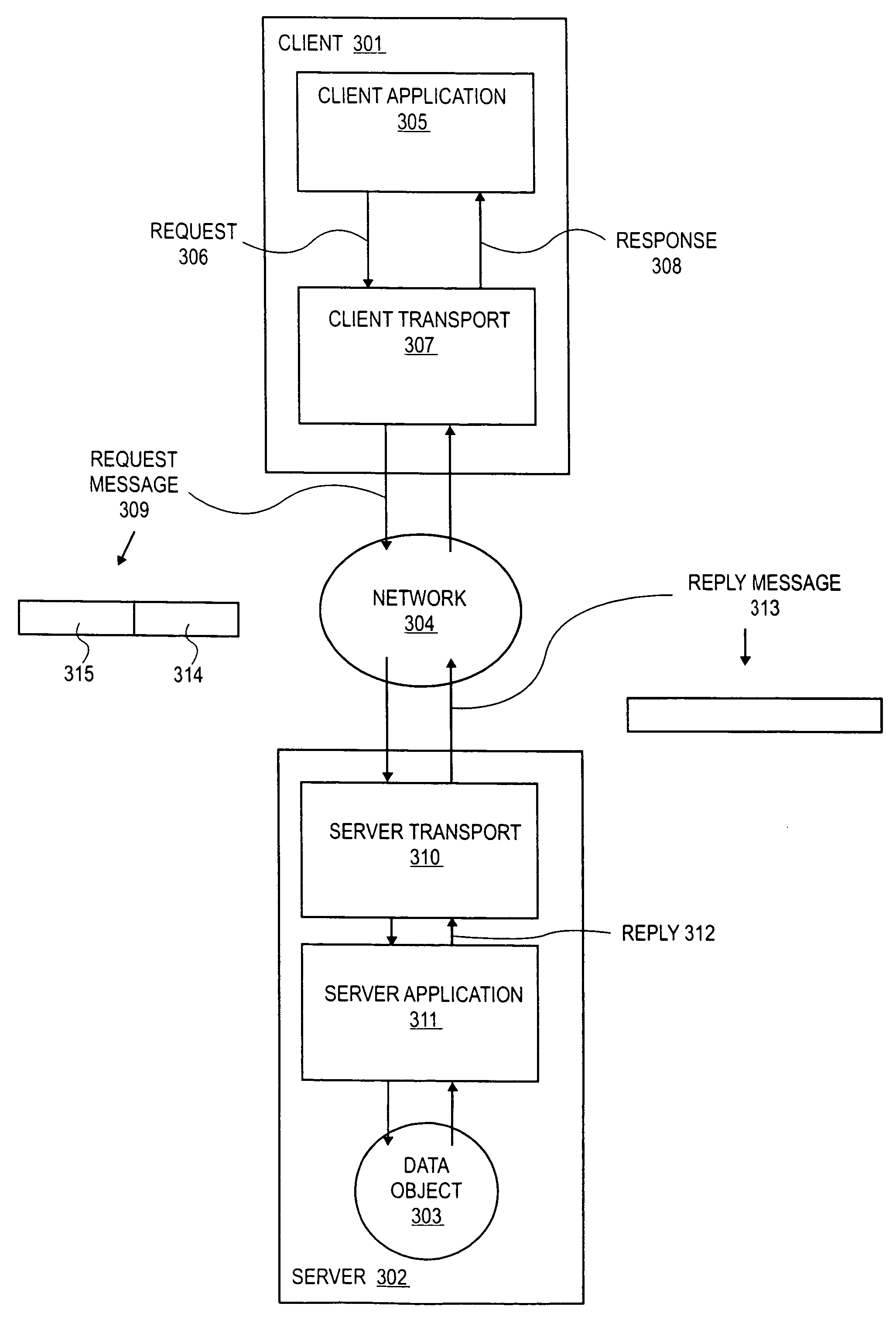
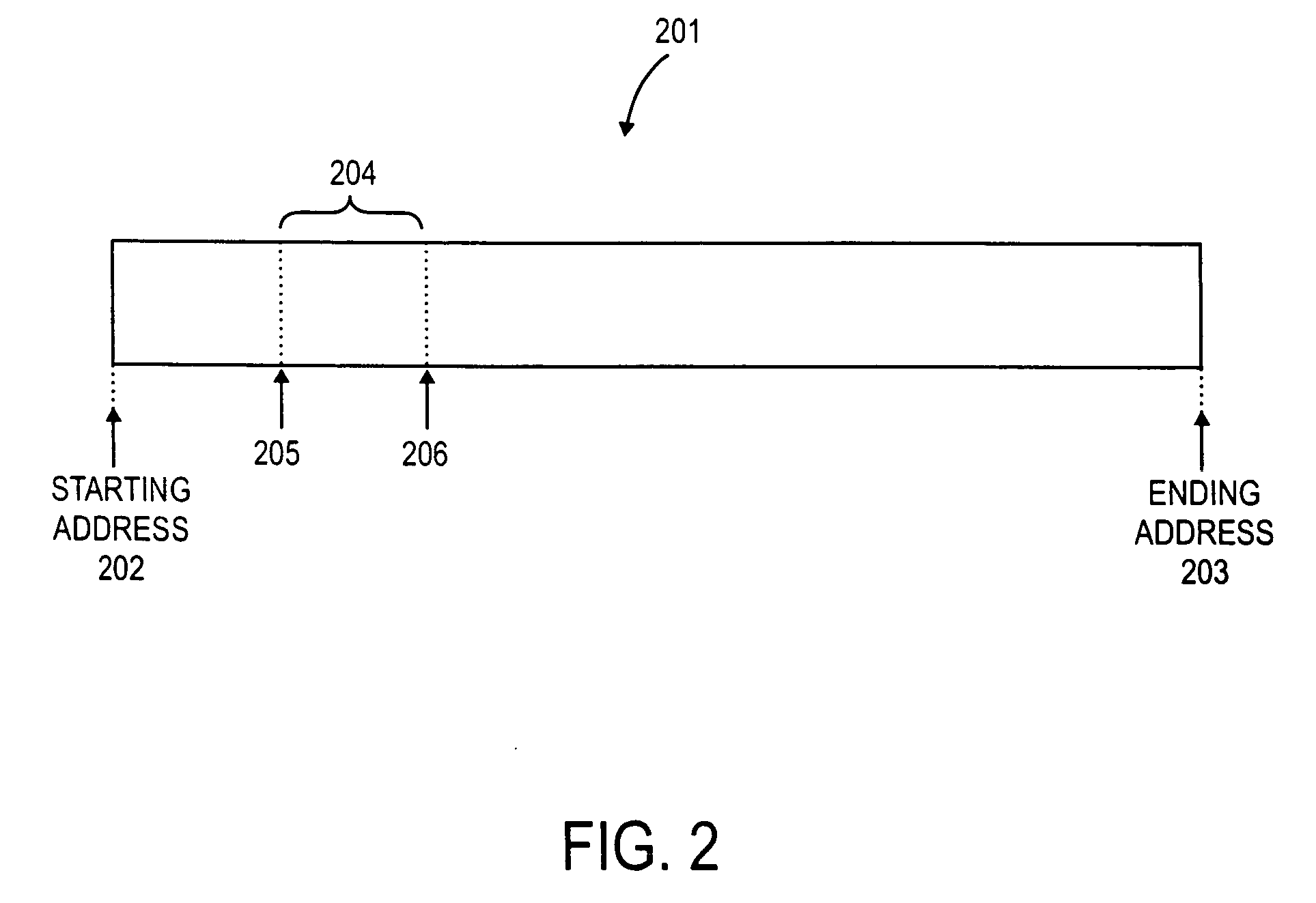
[0029] A method is described that limits data flow between two network nodes to an amount within a window where a first portion of data within a first segment of the window is separated from a second portion of data within a second segment of the window by a third portion of data not within the window.
1.0 Client Side State Management
a) Data Model Overview
[0030] A computer is any device having one or more processors that execute one or more software programs. A data object (or object) is any digital information resource that may be used by a computer program. Some examples of data objects include a data file, another computer program, an audio / video stream, an audio / video stream source, a software interface (e.g., a control interface and / or a data collection interface) to a remote or local physical device (e.g., a mechanical servo or measurement instrumentality).
[0031] An action is any action performed by a computer to or with an object. Some examples of an action include retrie...
PUM
 Abstract
Description
Claims
Application Information