Plasma display panel

Inactive Publication Date: 2007-02-08
SAMSUNG SDI CO LTD
View PDF2 Cites 7 Cited by
  • Summary
  • Abstract
  • Description
  • Claims
  • Application Information

AI Technical Summary

Benefits of technology

[0020] Also, the colors that are put in to the one colored member and the transparent thin layer may be complementary colors, which are mi

Problems solved by technology

Therefore, by making use of complementary colors as described above, it i

Method used


Image

  • Plasma display panel
  • Plasma display panel
  • Plasma display panel

Examples


Example

[0027] A plasma display panel (PDP) according to the present embodiments will now be described more fully hereinafter with reference to the accompanying drawings, in which exemplary embodiments are shown. Hereinafter, the same reference numbers are used to denote the same elements as in the Background of the Invention.

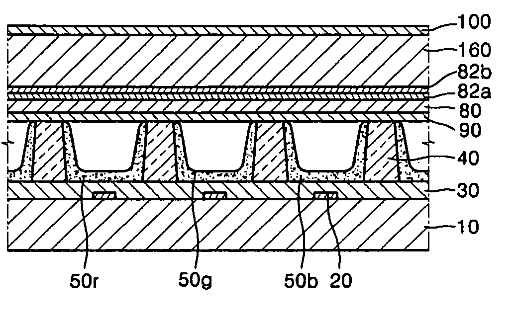
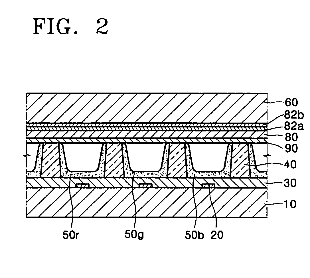
[0028]FIG. 4 is a cross sectional view of a PDP according to an exemplary embodiment.

[0029] Referring to FIG. 4, the PDP according to the present embodiment includes a colored front substrate 160 and a colored transparent thin layer 100, which is attached to a front surface of the front substrate 160. As can be seen from FIG. 4, a bus electrode 82b, for example, an indium tin oxide (ITO) electrode 82a, a front dielectric layer 80, barrier ribs 40, phosphor layers 50r, 50g, and 50b, a rear dielectric layer 30, address electrodes 20, and a rear substrate 10 are sequentially stacked on a rear surface of the front substrate 160 and may form a surface-discharge-type tri-e...


PUM


Abstract

Provided is a plasma display panel (PDP), which minimizes an elevation in reflection brightness caused by reflection of external light and improves in contrast and discharge efficiency. The PDP includes a front substrate transmitting visible rays; a rear substrate disposed substantially parallel to the front substrate; barrier ribs interposed between the front and rear substrates and defining a plurality of discharge cells along with the front and rear substrates, the barrier ribs formed of a dielectric material; two or more kinds of discharge electrodes disposed on at least one of the front substrate, the rear substrate, and the barrier ribs; a dielectric layer disposed on a rear surface of the front substrate; phosphor layers disposed in the discharge cells; and a discharge gas filled in the discharge cells. Herein, any two members of the front substrate, the dielectric layer, and the barrier ribs are colored, and when colors that are put in to the two members are mixed using subtractive mixture of colors, the mixed color lowers in both brightness and chroma.

Description

CROSS-REFERENCE TO RELATED APPLICATIONS [0001] This application claims the benefit of Korean Patent Application No. 10-2005-0070962, filed on Aug. 3, 2005, in the Korean Intellectual Property Office, the disclosure of which is incorporated herein in its entirety by reference. BACKGROUND OF THE INVENTION [0002] 1. Field of the Invention [0003] The present embodiments relate to a plasma display panel (PDP) used for a plasma display device, and more particularly, to a PDP that improves both contrast and discharge efficiency by reducing residual images and reflection of external light. [0004] 2. Description of the Related Art [0005]FIG. 1 is a fragmentary perspective view of a conventional PDP as disclosed in Japanese Patent Laid-Open Publication No. 1998-172442. [0006] As shown in FIG. 1, the conventional PDP includes an upper panel 1 and a lower panel 2, which are bonded to each other, and a space defined by the upper and lower panels 1 and 2 is filled with a discharge gas. The upper ...

Claims


Application Information

Patent Timeline
IPC IPC(8): H01J17/49H01J11/12H01J11/22H01J11/24H01J11/26H01J11/34H01J11/36H01J11/38H01J11/40H01J11/42H01J11/44
CPCH01J11/12H01J11/36H01J2211/444H01J11/44H01J11/38
Inventor KWEON, TAE-JOUNG
Owner SAMSUNG SDI CO LTD
Why Eureka
Try Eureka