Phase difference compensation element, liquid crystal display device and projection type image display device

Active Publication Date: 2019-08-01
DEXERIALS CORP
View PDF0 Cites 4 Cited by
  • Summary
  • Abstract
  • Description
  • Claims
  • Application Information

AI Technical Summary

Benefits of technology

[0024]According to the present invention, it is possible to provide a phase difference compensation element that can improve a contrast of

Problems solved by technology

However, in the negative C-plate described in Patent Document 1, a ratio of optical film thicknesses of two kinds of vapor-deposited films having different refractive indices is determined, and high-refractive-index layers having the same film thickness and low-refractive-index layers having the same film thickness determined based on the ratio are laminated alternately, resulting in a structural birefringence, which causes a phase difference.
For this reason, a total number of 80 or more layers are required to be laminated, and an antireflection film is required separately, so that there is concern about h

Method used


Image

  • Phase difference compensation element, liquid crystal display device and projection type image display device
  • Phase difference compensation element, liquid crystal display device and projection type image display device
  • Phase difference compensation element, liquid crystal display device and projection type image display device

Examples


Example

Example 1

[Fabrication of Phase Difference Compensation Element]

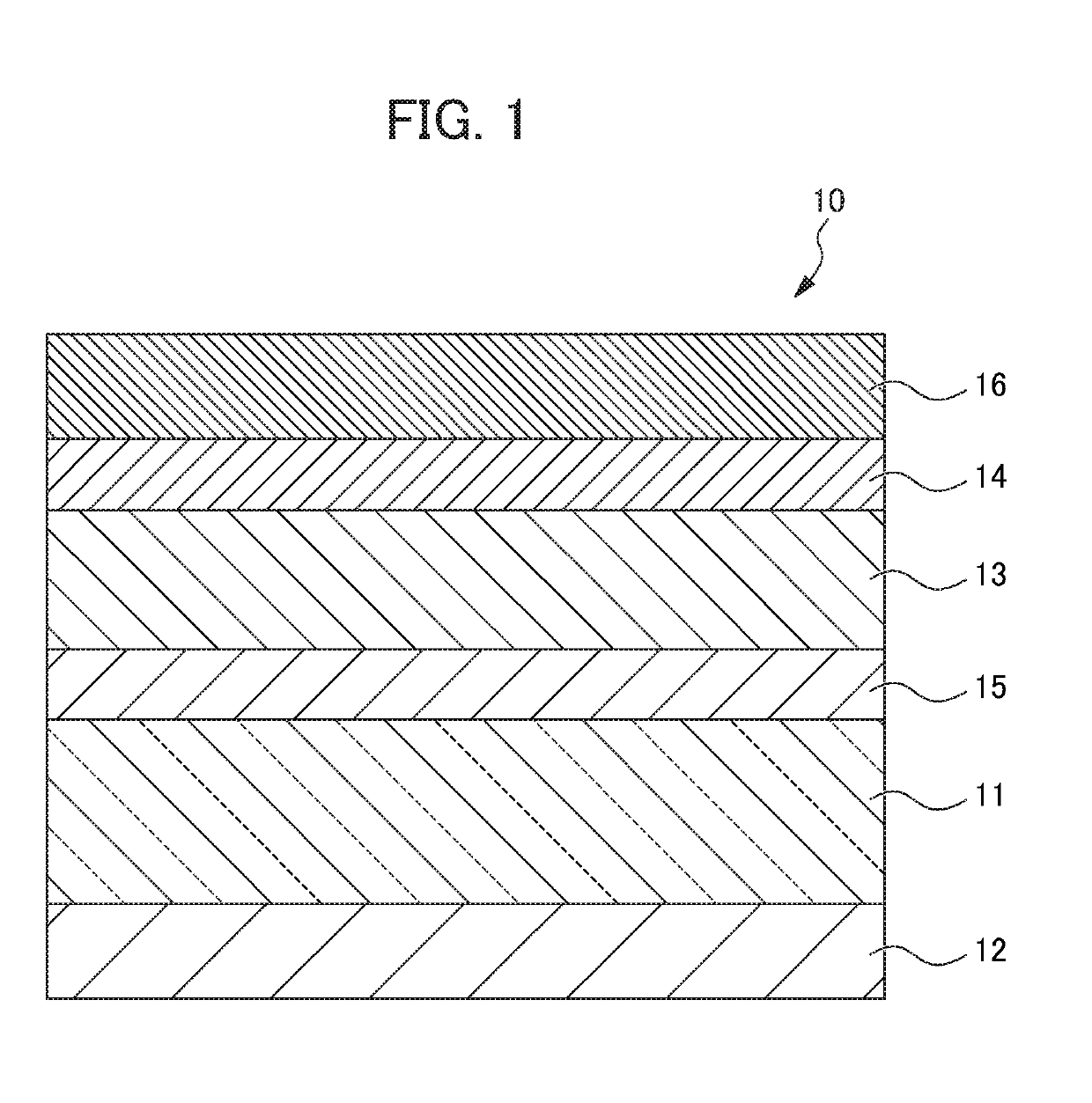
(Fabrication of Matching Layer)

[0074]A glass substrate (having an average thickness of 0.7 mm) was prepared and three layers of SiO2 / Nb2O5 / SiO2 were laminated on one surface of the substrate by a sputtering method, thereby forming a matching layer.

(Fabrication of Phase Difference Providing Antireflection Layer)

[0075]Subsequently, 34 layers were alternately laminated on the other surface of the glass substrate by the sputtering method using Nb2O5 and SiO2, thereby forming a phase difference providing antireflection layer. The provided phase difference was made 7.0 nm with respect to incident light tilted at 15° from a normal direction of the substrate.

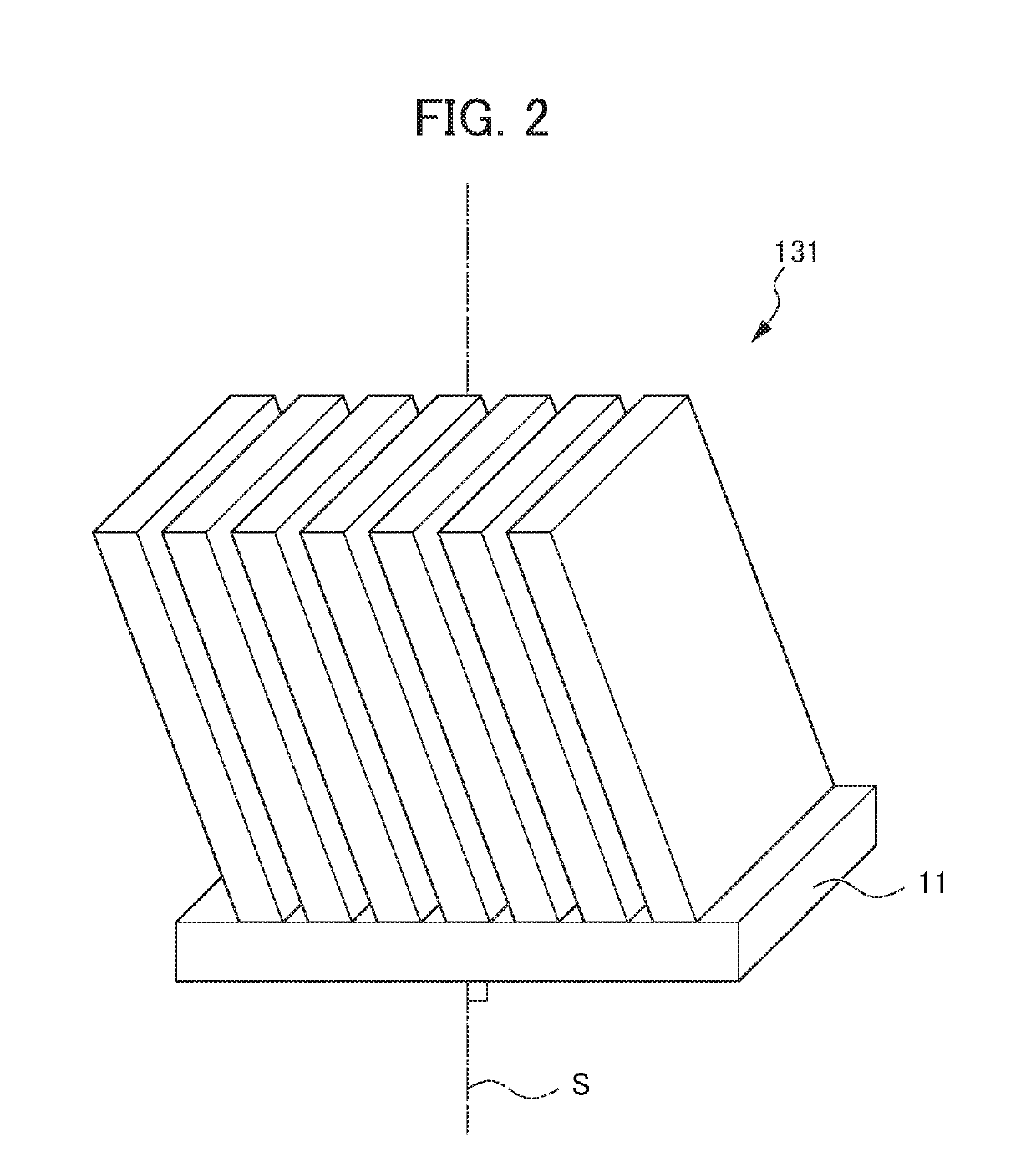
(Fabrication of Optical Anisotropic Layer)

[0076]A vapor deposition source was disposed at a position tilted at an angle of 70° with respect to the substrate normal direction using a mixture of Ta2O5 and TiO2 as vapor deposition material on the matching layer, a plurality of ...

Example

Comparative Example 1

[0079]The phase difference compensation element was fabricated in the same manner as Example 1, except that the oblique vapor deposition was performed with the vapor deposition angle of the vapor deposition process 1 in Example 1 being changed by 1° in a range of ±5° from 83° which is the in-plane vapor deposition angle of Example 1.

Example

Comparative Example 2

[0080]The phase difference compensation element was fabricated in the same manner as Example 1, except that the vapor deposition was performed with the vapor deposition angle of the vapor deposition process 2 in Example 1 being changed by 1° in a range of ±5° from 103° which is the in-plane vapor deposition angle of Example 1.


PUM


Abstract

Provided is a phase difference compensation element that can improve a contrast of a liquid crystal display device and has durability while suppressing an increase in cost and prolongation of lead time. The phase difference compensation element is formed so that, when an optical anisotropic layer is formed on a substrate, the optical anisotropic layer includes a plurality of birefringent films, and a direction of a combined vector obtained by combining respective vectors of the birefringent films when determining a vector with a direction of a line segment obtained by projecting a film formation direction of each birefringent film on a surface of a transparent substrate and a thickness, is substantially the same as a direction of a line segment obtained by projecting a liquid crystal molecule constituting a liquid crystal cell on the surface of the transparent substrate.

Description

[0001]This application is based on and claims the benefit of priority from Japanese Patent Application No. 2018-15822, filed on 31 Jan. 2018, the content of which is incorporated herein by reference.BACKGROUND OF THE INVENTIONField of the Invention[0002]The present invention relates to a phase difference compensation element, a liquid crystal display device and a projection type image display device.Related Art[0003]In recent years, in liquid crystal display devices, an optical compensation technique using a phase difference compensation element is used to improve contrast characteristics and viewing angle characteristics. As such a phase difference compensation element, for example, a phase difference compensation element has been proposed in which a negative C-plate formed by laminating high-refractive-index thin films and low-refractive-index thin films alternately by vapor deposition of dielectric material and an O-plate formed of an obliquely vapor-deposited film configured by ...

Claims


Application Information

Patent Timeline
IPC IPC(8): G02F1/13363G02B5/30G02B1/115G02B1/14
CPCG02F1/13363G02B5/3083G02B1/115G02B1/14G03B21/006G02F1/133632G02F2413/10G02F1/133742G02F1/133638
Inventor SUGAWARA, JUNICHI
Owner DEXERIALS CORP
Why Eureka
Try Eureka