Front sheet and display device using the same

Inactive Publication Date: 2007-12-06
MAXELL HLDG LTD
View PDF10 Cites 5 Cited by
  • Summary
  • Abstract
  • Description
  • Claims
  • Application Information

AI Technical Summary

Benefits of technology

[0011] With the above structure, the display panel's inherent directional characteristics in the horizontal direction are maintained properly while deterioration in the front sheet's transmittance for outgoing light is suppressed. In addition, since t

Problems solved by technology

When the lenticular lenses as described by the former techniques are used, it is difficult to focus radial light rays on the light-transmitting area between

Method used


Image

  • Front sheet and display device using the same
  • Front sheet and display device using the same
  • Front sheet and display device using the same

Examples


Example

First Embodiment

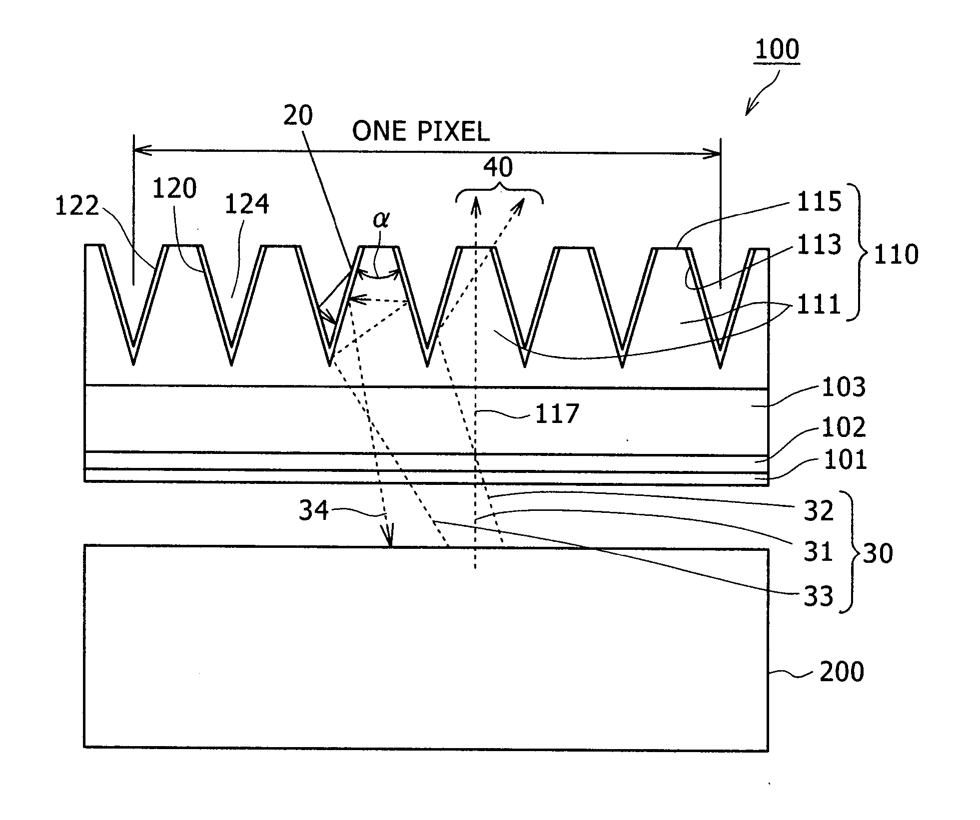
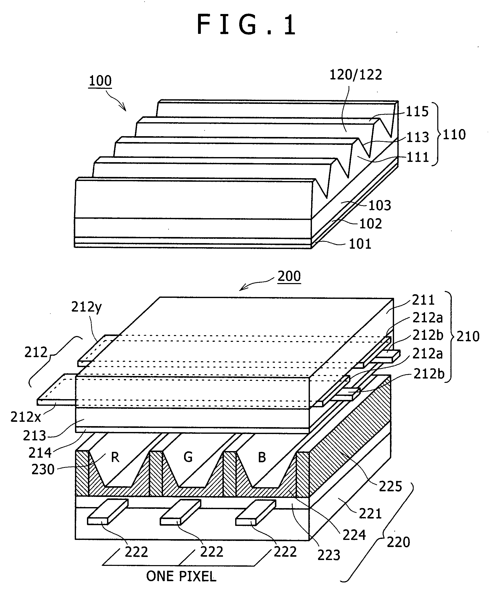
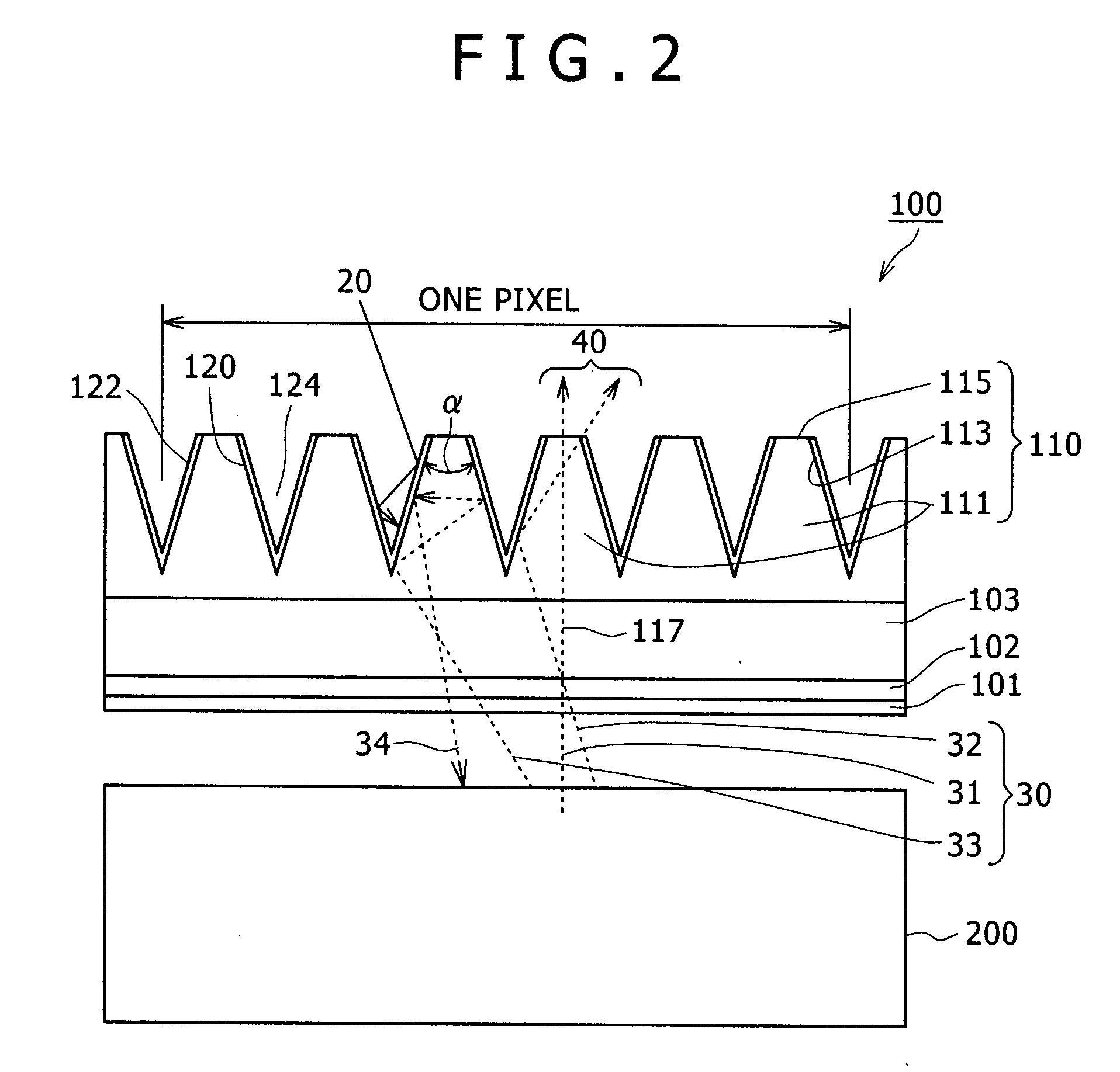
[0026]FIG. 1 is a perspective view of the main part of a display device according to a first embodiment of the present invention. To facilitate understanding of the PDP structure, FIG. 1 shows an upper panel and a lower panel separately.

[0027] As illustrated in FIG. 1, a front plate 100 is located in front of a PDP 200 at a given distance from it. First, the structure of the PDP 200 is explained below.

[0028] The PDP 200 includes an upper panel 210 and a lower panel 220 which are opposite to each other. First, an explanation is given of the upper panel 210. The upper panel 210 has an upper glass substrate 211 as a display side substrate on which display electrodes 212 extend horizontally in a striped pattern. The display electrodes 212 include an X display electrode (also called a common electrode) 212x and a Y display electrode (also called a scanning electrode) 212y which are opposite and parallel to each other constituting a pair where each display electrode con...

Example

Second Embodiment

[0054] Next, a second embodiment of the invention will be described referring to FIGS. 4 and 5.

[0055]FIG. 4 schematically shows directional characteristics in the screen vertical direction in connection with the shape of the lateral inclined portion of the light guide.

[0056] In FIG. 4, characteristic curve 193 represents directivity without a light guide array sheet and characteristic curve 191 represents directivity with the light guide array sheet 110 according to the first embodiment. As shown in FIG. 4, directivity in the screen vertical direction for the light guide array sheet with a virtually trapezoidal cross section in the first embodiment is narrow. The light guide shape according to the second embodiment which provides a broader directivity 192 than the directivity 191 will be described below.

[0057]FIG. 5 schematically shows part of the cross section of a light guide according to the second embodiment in the screen vertical direction.

[0058] As shown ...

Example

Third Embodiment

[0059] Although in the first embodiment the light-absorbing layer 122 lies covering the metal reflection layer 120 formed on the inclined portion 113 of the light guide 111, the present invention is not limited thereto.

[0060]FIG. 6 schematically shows the cross section of a display device according to the third embodiment in the PDP screen vertical direction. As in FIG. 2, an area for one pixel (unit pixel) is indicated here. In FIG. 6, elements with the same functions as those in FIG. 2 are designated by the same reference numerals and their descriptions are omitted.

[0061] As apparent from FIG. 6, in a front plate 100A according to the third embodiment, black light absorber 130 is filled in the recess 124 instead of the light-absorbing layer 122 which covers the metal reflection layer 120 of the front plate 100 in the first embodiment in order to absorb external light. The other features are the same as in the first embodiment.

[0062] In this embodiment, since th...


PUM


Abstract

A technique for a display device using a display panel with Lambert light distribution, such as a plasma display panel, which displays a bright image with less contrast deterioration. This device has a front sheet which is integrally or separately located in front of the display panel. The front sheet includes light guides which extend in the horizontal direction and have a virtually convex cross section in the vertical direction with their apexes on the light exit side. A light reflection layer and a light-absorbing layer are sequentially stacked on the lateral sides of the light guides.

Description

CLAIM OF PRIORITY [0001] The present application claims priority from Japanese application serial no. JP 2006-138435, filed on May 18, 2006, the content of which is hereby incorporated by reference into this application. BACKGROUND OF THE INVENTION [0002] (1) Field of the Invention [0003] The present invention relates to a front sheet on the front side of a display panel such as a plasma display panel (PDP) and a display device using the same. [0004] (2) Description of the Related Art [0005] In a display device which uses a light-emitting display panel such as the plasma display panel (PDP) and a field emission display (FED), a front sheet (also called an optical filter) is attached to the front side of the display panel in order to improve contrast in a bright room by reduction of external light reflection. [0006] Japanese Patent Application Laid-Open Publication No. 2001-154597 and Japanese Patent Application Laid-Open Publication No. 2005-129532 describe this kind of front sheet....

Claims


Application Information

Patent Timeline
IPC IPC(8): F21V7/04G02B5/00G02B5/02G02B5/20G09F9/00
CPCH01J11/12H01J11/44H05K9/0096H01J2211/446H01J2211/442
Inventor HIRATA, KOJIADACHI, KEI
Owner MAXELL HLDG LTD
Why Eureka
Try Eureka