Space optical transmission apparatus and space optical transimission system

a technology of space optical transmission and apparatus, applied in the direction of electrical apparatus, electromagnetic transmission, satellite communication transmission, etc., can solve the problems of complex whole system, inability to provide space optical transmission apparatus, and inability to perform high-speed space optical transmission with respect to the terminal, so as to avoid a complicated configuration of the whole apparatus and system

Inactive Publication Date: 2007-02-08
PANASONIC CORP
View PDF2 Cites 7 Cited by
  • Summary
  • Abstract
  • Description
  • Claims
  • Application Information

AI Technical Summary

Benefits of technology

[0009] Therefore, an object of the present invention is to provide a space optical transmission apparatus and a space optical transmission system which achieve high-speed simultaneous space optical transmission with respect to a plurality of terminals while avoiding a complicated configuration of the whole apparatus and system.

Problems solved by technology

Therefore, in the conventional space optical transmission system, there is a limitation on the power of optical signals transmitted to the terminals 811a, 811b and 811c, so that high-speed space optical transmission cannot be performed with respect to the terminals 811a, 811b and 811c.
In addition, in the conventional space optical transmission system of FIG. 9, a large number of space optical transmission apparatuses 911a, 911b and 911c need to be provided in the vicinity of the center base 910, so that the whole system tends to be complicated, and it is difficult to secure a place for providing the space optical transmission apparatuses 911a, 911b and 911c.

Method used


Image

  • Space optical transmission apparatus and space optical transimission system
  • Space optical transmission apparatus and space optical transimission system
  • Space optical transmission apparatus and space optical transimission system

Examples


first embodiment

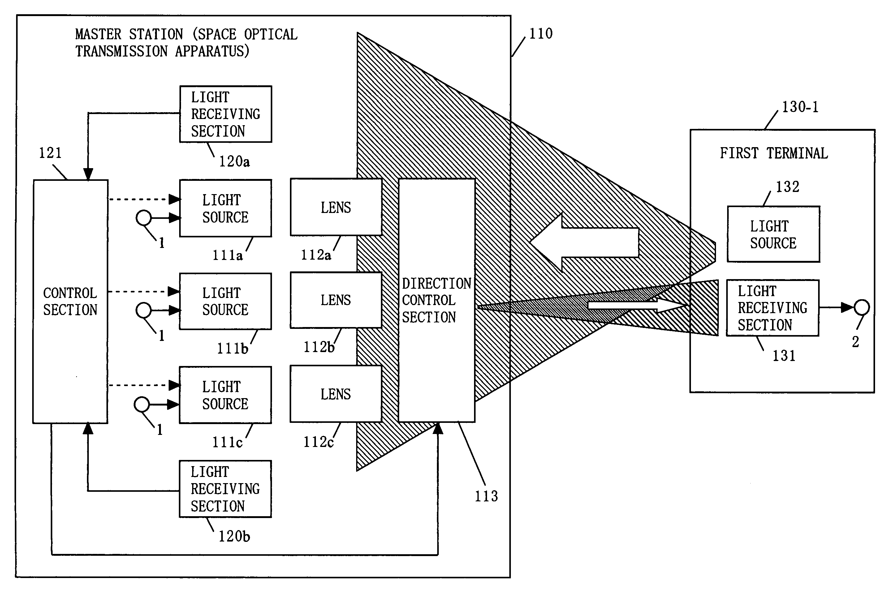
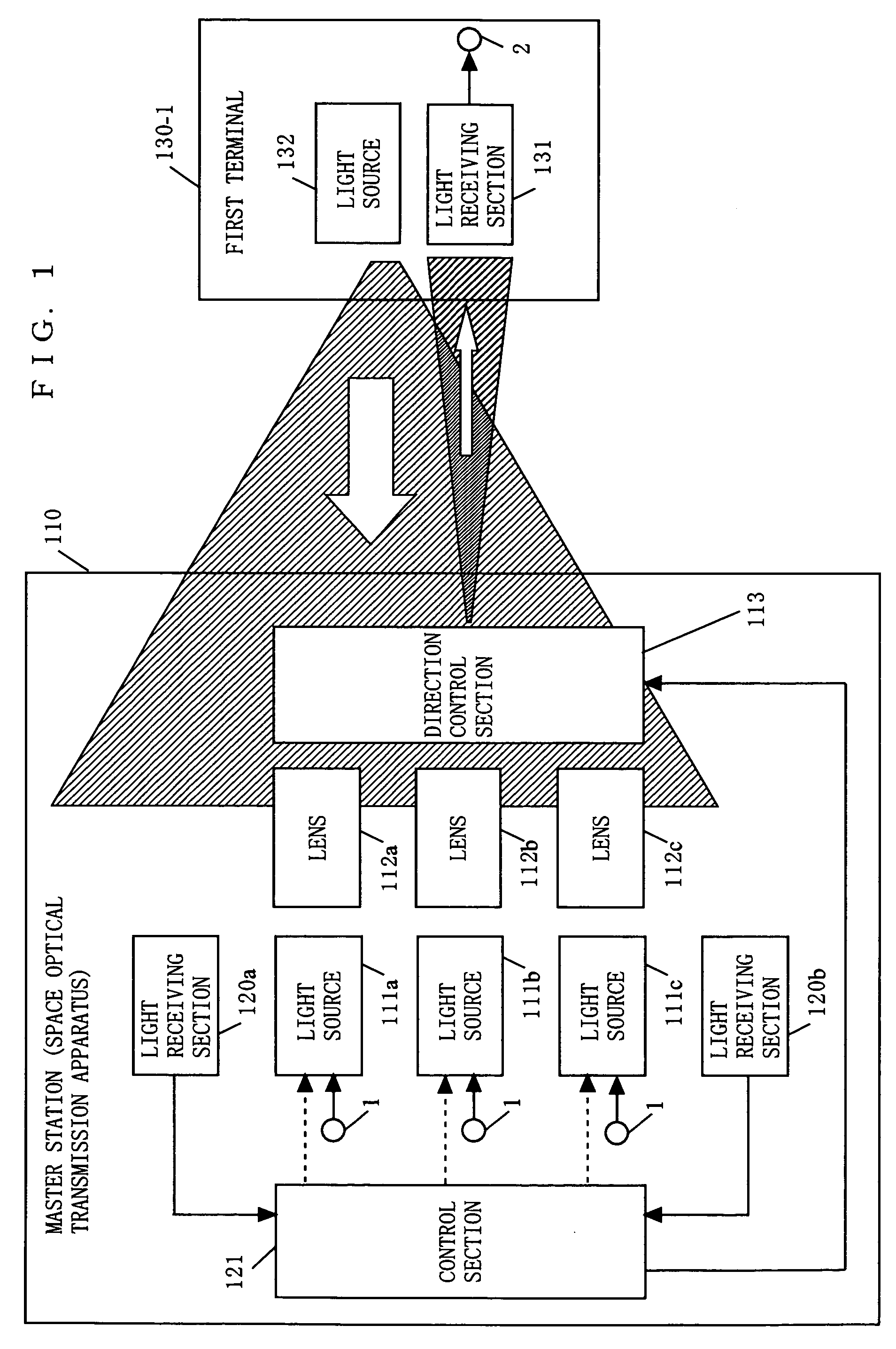
[0037]FIG. 1 is a block diagram illustrating an exemplary configuration of a space optical transmission system according to a first embodiment of the present invention. In FIG. 1, the space optical transmission system of the present invention is composed of a space optical transmission apparatus 110 and a first terminal 130-1. Note that the space optical transmission apparatus is hereinafter referred to as a master station. Also, the first terminal 130-1 is simply referred to as a terminal 130-1. The master station 110 communicates with the terminal 130-1 by space optical transmission. The master station 110 comprises an input terminal 1, a plurality of light sources 111a, 111b and 111c, a plurality of lenses 112a, 112b and 112c, a direction control section 113, a plurality of light receiving sections 120a, 120b and 120c (the light receiving section 120c is not shown), and a control section 121. The terminal 130-1 comprises a light receiving section 131, a light source 132, and an o...

second embodiment

[0048]FIG. 3 is a block diagram illustrating an exemplary configuration of a space optical transmission system according to a second embodiment of the present invention. In FIG. 3, a master station 310 has a configuration different from that of the master station 110 of FIG. 1 in that the light receiving sections 120b and 120c are removed. The other parts of the master station 310 are indicated with the same reference numerals as those of the master station 110 of FIG. 1 and will not be described. A third terminal 330 comprises a plurality of light receiving sections 131a, 131b and 131c, a light source 132, a location information specifying section 331, and an output terminal 2. Note that the third terminal 330 is hereinafter referred to as a terminal 330.

[0049] An operation of the space optical transmission system of the second embodiment of the present invention will be described with reference to FIG. 3. In FIG. 3, when the terminal 330 wants to communicate with the master stati...

third embodiment

[0055]FIG. 4 is a block diagram illustrating an exemplary configuration of a master station 410 according to a third embodiment of the present invention. The master station 410 of FIG. 4 is different from the master station 310 of FIG. 3 in that a data switch section 411, a plurality of code generating sections 412a, 412b and 412c, and a plurality of modulation sections 413a, 413b and 413c are further provided. The other parts of the master station 410 are indicated with the same reference numerals as those of the master station 310 of FIG. 3 and will not be described.

[0056]FIG. 5 is a block diagram illustrating an exemplary configuration of a terminal 530 according to a third embodiment of the present invention. In FIG. 5, the fourth terminal 530 is different from the terminal 130-1 of FIG. 1 in that a demodulation section 511 is further provided. The other parts of the fourth terminal 530 are indicated with the same reference numerals as those of the terminal 130-1 of FIG. 1 and ...


PUM


Abstract

A space optical transmission apparatus is provided which achieves high-speed simultaneous space optical transmission with respect to a plurality of terminals. In the space optical transmission apparatus, a light receiving section receives an optical signal from a terminal. A control section estimates how much optical axes of a master station and the terminal are deviated from each other, based on the received optical signal. The control section selects one of a plurality of light sources which requires a smallest amount of shift of an optical axis thereof, based on the estimated optical axis deviation amount, so as to communicate with the terminal.

Description

BACKGROUND OF THE INVENTION [0001] 1. Field of the Invention [0002] The present invention relates to a space optical transmission apparatus and a space optical transmission system for transmitting an optical signal via free space. More particularly, the present invention relates to a space optical transmission apparatus and a space optical transmission system for achieving simultaneous communication with a plurality of terminals. [0003] 2. Description of the Background Art [0004] In the field of free-space optical transmission, for example, Japanese Patent Laid-Open Publication No. 2003-309524 (hereinafter referred to as Patent Document 1) discloses a conventional space optical transmission system which achieves communication between a master station and a plurality of terminals. In the conventional space optical transmission system disclosed in Patent Document 1, an optical signal output from a light source provided in the master station is reflected and divided into a plurality of...

Claims


Application Information

Patent Timeline
Patent Type & Authority Applications(United States)
IPC IPC(8): H04B10/00
CPCH04B10/118
Inventor SASAI, HIROYUKIIEDA, TOMOAKIHASE, KAZUTOSHI
Owner PANASONIC CORP
Why Eureka
Try Eureka