Device for removing sand from casting

a technology for casting sand and casting, which is applied in the field of casting shakeout, can solve the problems of only local collapse of casting sand inside the casting, and insufficient collapse of casting sand over the entire portion inside the casting

Inactive Publication Date: 2007-02-15
KUBUSHIKI KAISHA AOYAMA
View PDF0 Cites 18 Cited by
  • Summary
  • Abstract
  • Description
  • Claims
  • Application Information

AI Technical Summary

Problems solved by technology

However, since this is not enough to separate the casting sand from the casting or to collapse the casting sand, impact is applied by a hammer to ensure satisfactory shakeout.
However, the impact is applied by the hammer to only one portion of the casting, and is not applied by hitting the most effective portion.
Thus, the impact applied to the casting propagates only a part of the casting, and the casting sand solidified inside the casting is only locally collapsed.
Therefore, there is a problem that the casting sand over the entire portion inside the casting is not sufficiently collapsed.

Method used


Image

  • Device for removing sand from casting
  • Device for removing sand from casting
  • Device for removing sand from casting

Examples


Embodiment Construction

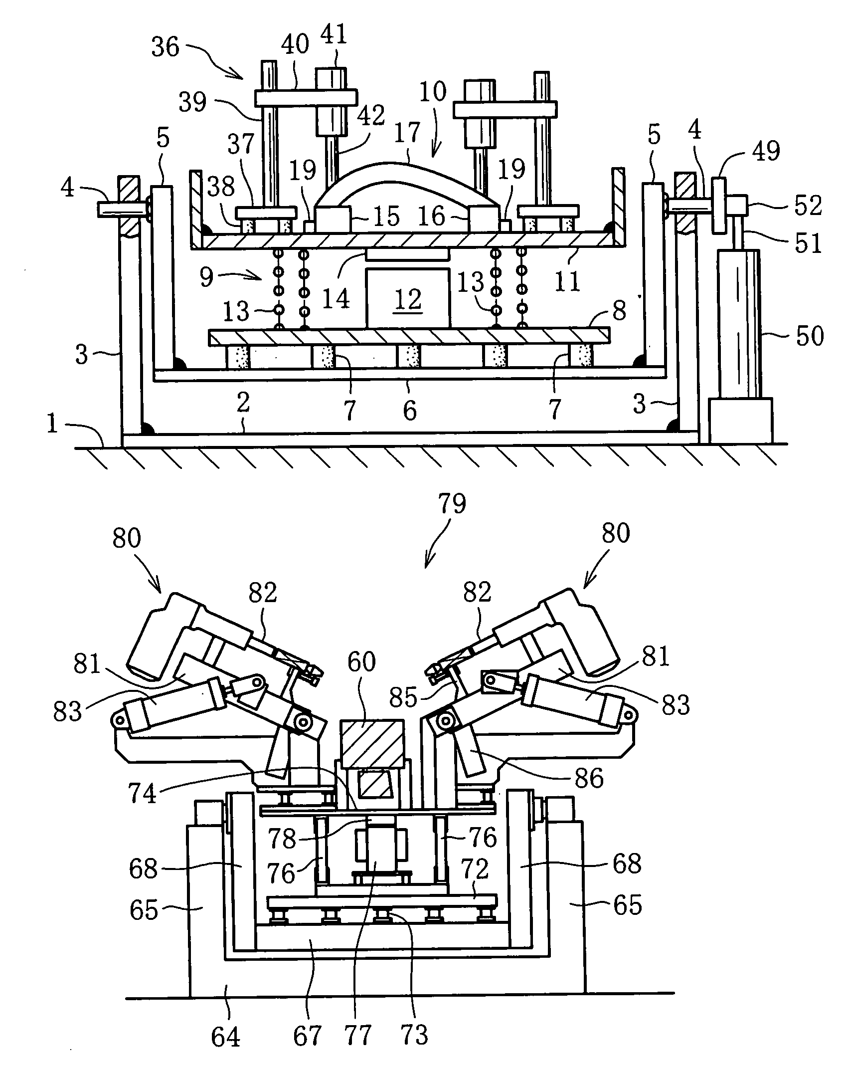
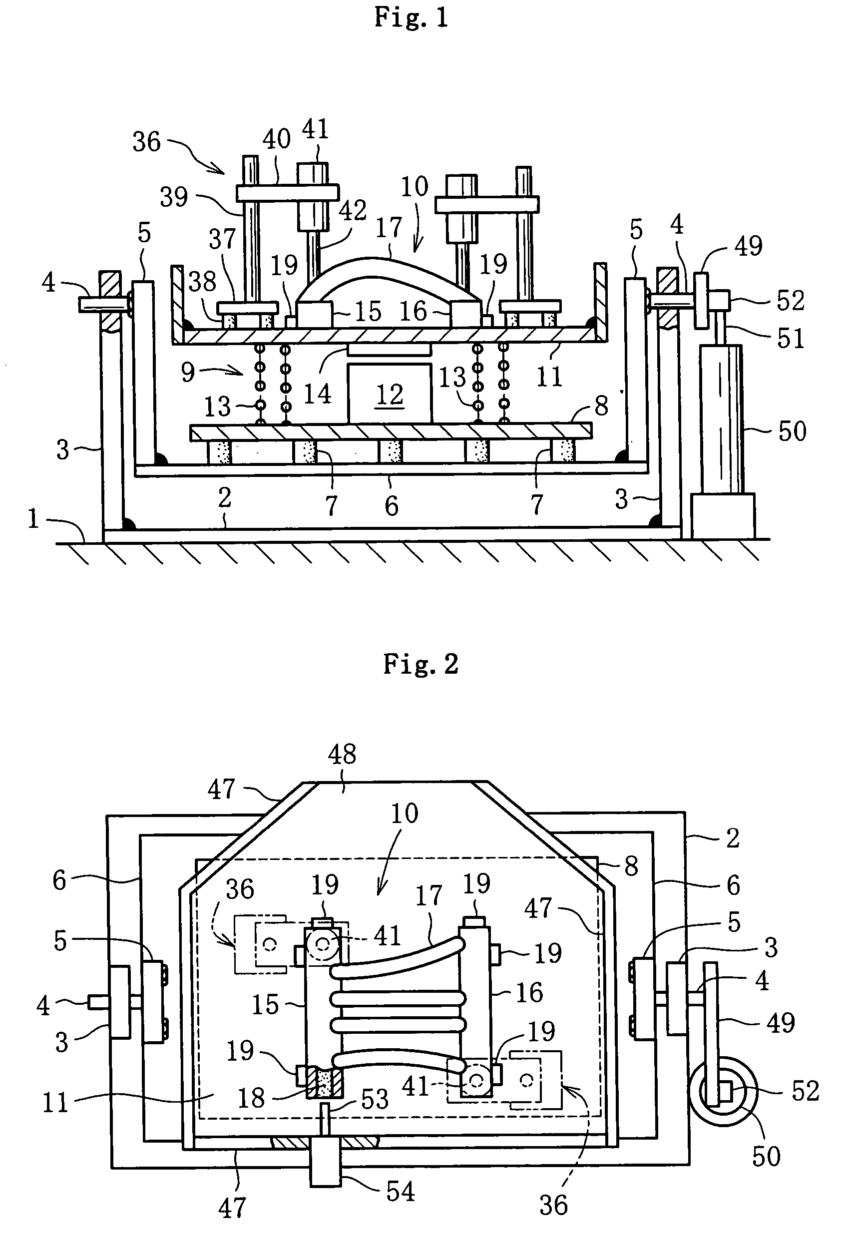
[0043] Referring to FIGS. 1 and 2, a base plate 2 made of iron is placed on floor 1, and struts 3 are firmly fixed to the left and right sides of the base plate 2 by means of welding or other method. A supporting shaft 4 is rotatably attached to the upper portion of the struts 3, and a supporting arm 5 is firmly fixed to the supporting shaft 4. A first supporting plate 6 is fixed to the lower portions of the supporting arms 5. On the upper side of the first supporting plate 6, a second supporting plate 8 is attached via a number of elastic members 7, which will be described later, as shown in FIG. 5. A vibration generating unit 9 serving as vibrating means is placed on the second supporting plate 8.

[0044] The vibration generating unit 9 continuously generates vibration, and a supporting member 11 for supporting a casting 10 is supported by the vibration generating unit 9. The vibration generating unit 9 is of a commonly employed type and is composed of an electromagnet 12 which gen...


PUM

PropertyMeasurementUnit
rotation angleaaaaaaaaaa
electromagnetic attractive forceaaaaaaaaaa
thickaaaaaaaaaa

Abstract

A casting shakeout apparatus comprises: a first unit for vibrating a supporting member on which a casting is placed and a second unit for applying impact or vibration to the casting, wherein the second unit can move between two positions, one of which is an evacuation position for allowing the casting to be loaded and unloaded and a work position for applying impact or vibration.

Description

TECHNICAL FIELD [0001] The present invention relates to casting shakeout, in which vibration applied to a casting and a phenomenon caused in the casting by the vibration are organically linked to effectively perform the shakeout. BACKGROUND ART [0002] The conventional technology considered to be closest to the present invention is one disclosed in the publication of Japanese Patent No. 3128735. The principal characteristic of this technology is that one portion of a casting under a vibrating state is hit with a hammer. In this conventional technology, vibration is applied to the whole casting sand inside the casting by bringing the whole casting into a vibrating state. However, since this is not enough to separate the casting sand from the casting or to collapse the casting sand, impact is applied by a hammer to ensure satisfactory shakeout. However, the impact is applied by the hammer to only one portion of the casting, and is not applied by hitting the most effective portion. Thus...

Claims


Application Information

Patent Timeline
Patent Type & Authority Applications(United States)
IPC IPC(8): B22D29/00B22D45/00B22D47/00
CPCB22D29/005
Inventor AOYAMA, YOSHITAKAAOYAMA, SHOJI
Owner KUBUSHIKI KAISHA AOYAMA
Why Eureka
Try Eureka