Cable connector assembly with EMI gasket
a cable connector and gasket technology, applied in the direction of coupling device connection, substation/switching arrangement details, engagement/disengagement of coupling parts, etc., can solve the problems of unsuitable grounding element types, inconvenient connection between the emi gasket and the cable connector assembly
- Summary
- Abstract
- Description
- Claims
- Application Information
AI Technical Summary
Benefits of technology
Problems solved by technology
Method used
Image
Examples
first embodiment
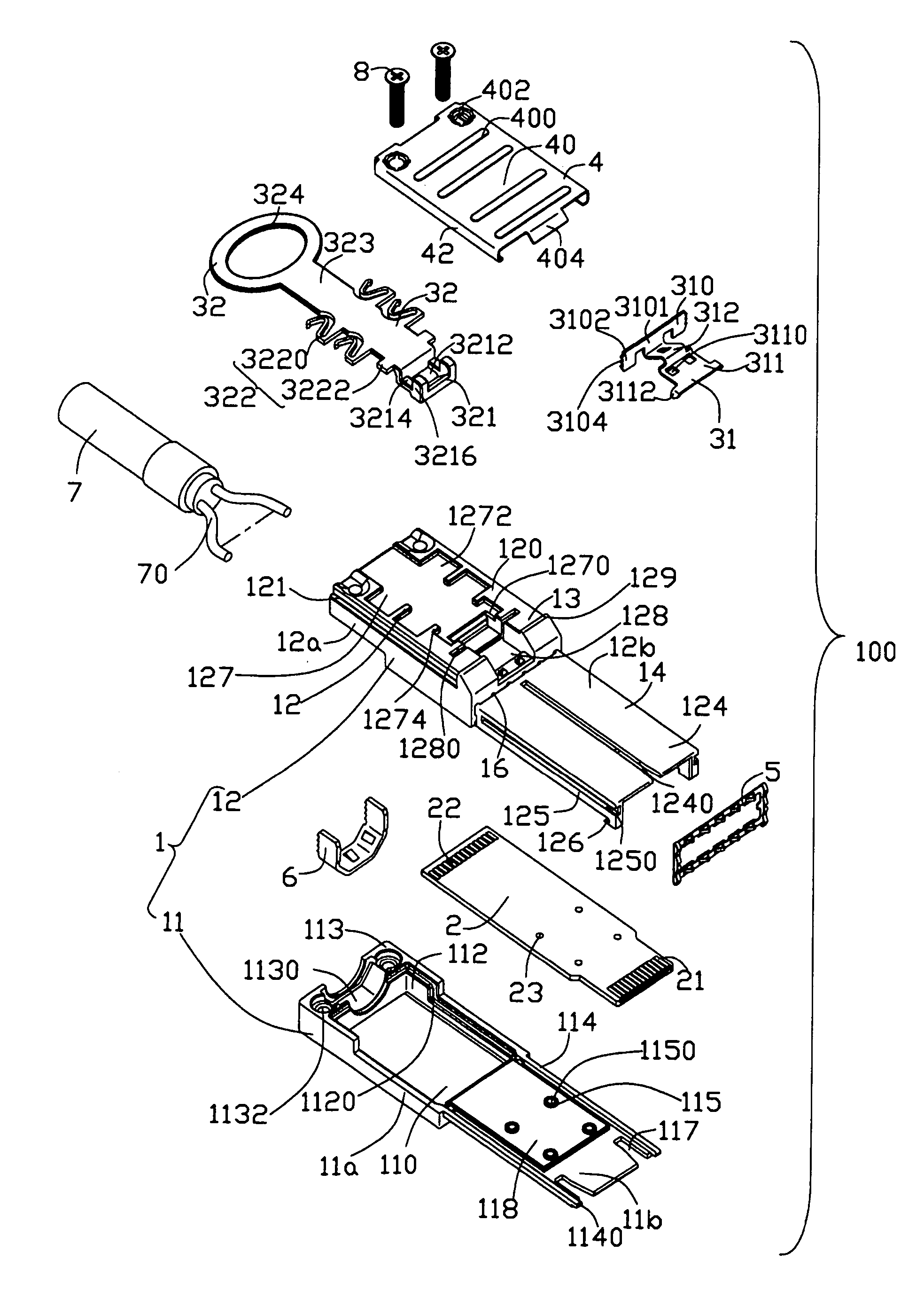
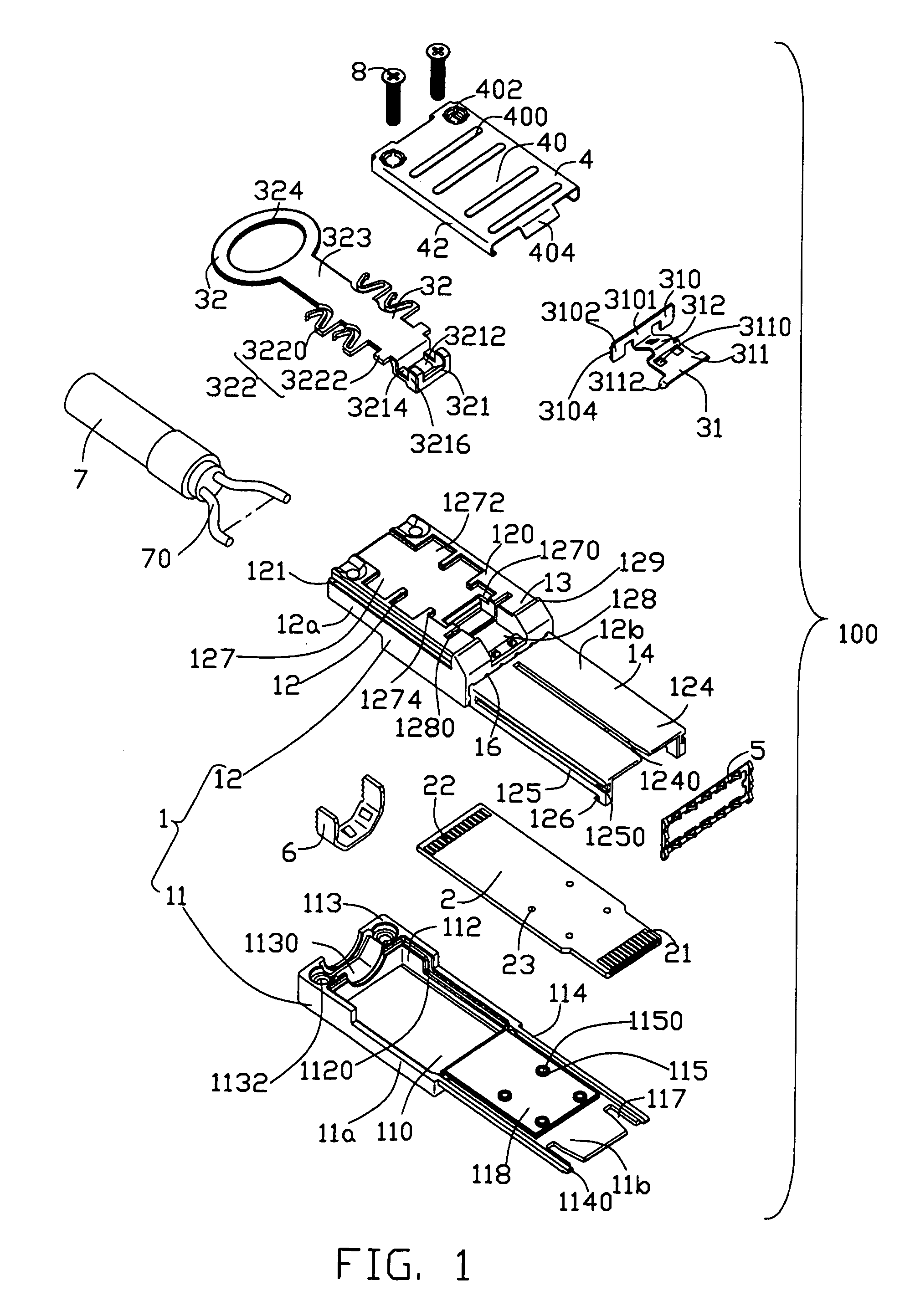
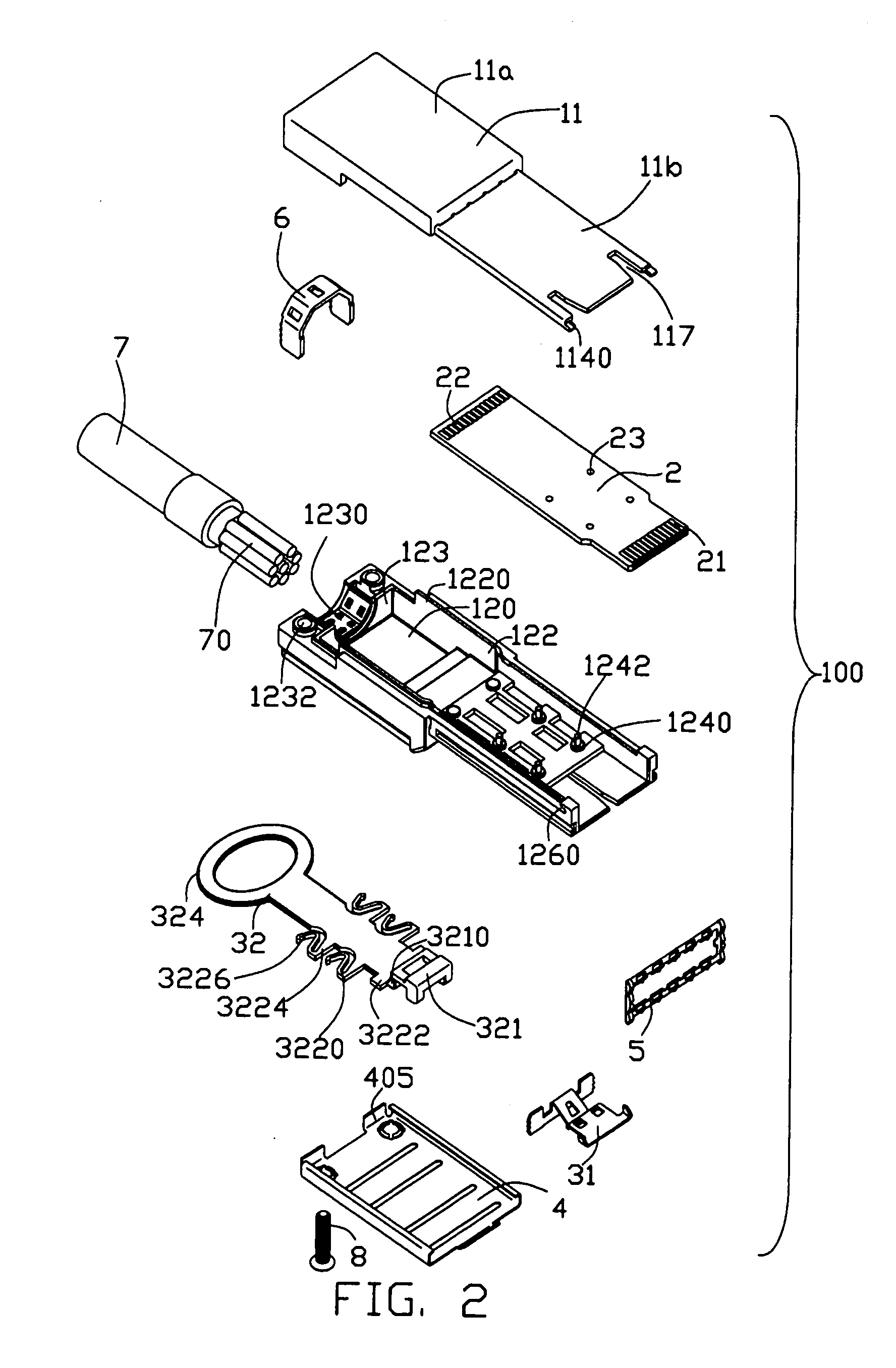
[0028] Referring to FIGS. 1-4, a cable connector assembly 100 in accordance with the present invention comprises a housing 1, a printed circuit board (PCB) 2 located in the housing 1, a cable 7 with a cable holder 6 electrically connecting with the PCB 2, a latch mechanism 3 assembled to the housing 1, a metal shell 4 assembled to the housing 1 to partially cover the latch mechanism 3.
[0029] Please refer to FIGS. 1-8, the housing 1 of the present invention is made of metal material and comprises a base 11, a cover 12 engagble with the base 11 and a receiving space 15 formed between the base and the cover 11, 12. The metal housing 1 also comprises a rectangular base portion 13 and an elongated tongue portion 14 extending forwardly from the base portion 13.
[0030] The base 11 comprises a first base section 11a and a first tongue section 11b extending forwardly from the first base section 11a. The first base section 11a comprises a first flat portion 110, a pair of first flanges 112 an...
second embodiment
[0043] A cable assembly 200 of the present invention is illustrated in FIGS. 15-18. The difference between the cable assemblies 100, 200 exists in the latch mechanisms 3, 3′. Thus, the description of the same members is omitted here and some same members are omitted in the drawing figures.
[0044] Referring to FIGS. 15-16, the latch mechanism 3′ of the cable assembly 200 has the substantially same structure as that of the latch mechanism 3 of the cable assembly 100. The latch mechanism 3′ also comprises a latch member 31′ and a pulling member 32′ cooperating with the latch member 31′. The latch member 31′ comprises a U-shape engaging portion 310′ located in a vertical surface, the flat latching portion 311 located in a horizontal surface perpendicular to the vertical surface and the inclined connecting portion 312 connecting the engaging portion 310′ with the latching portion 311. The latching portion 311 and the connecting portion 312 have the same structures as those of the latch me...
third embodiment
[0048] Referring to FIGS. 19-22, a cable connector assembly 300 in accordance with the present invention is illustrated. The latch mechanism 3″ of the cable connector assembly 300 also comprises a latch member 31″ and a pulling member 32″ cooperating with the latch member 31″. Same members and structure description are omitted in the specification and in the drawing figures.
[0049] Referring to FIGS. 19-20, tip end of the cooperating portion 321″ of the pulling member 32″ is enlarged and forms an inclined surface 3210″ for latching with the latch member 31″.
[0050] The latch member 31″ comprises a flat connecting portion 312″ formed with a pair of rectangular holes 3120″, a latch section 311″ upwardly then flatly extending from a front edge of the connecting portion 312″, an H-shape engaging portion 310″ vertically extending from a rear edge of the connecting portion 312″, and an inclined portion 313′ upwardly and rearward extending from a middle of the engaging portion 310″. The eng...
PUM
 Abstract
Description
Claims
Application Information
 - R&D
- Intellectual Property
- Life Sciences
- Materials
- Tech Scout
- Unparalleled Data Quality
- Higher Quality Content
- 60% Fewer Hallucinations
Browse by: Latest US Patents, China's latest patents, Technical Efficacy Thesaurus, Application Domain, Technology Topic, Popular Technical Reports.
© 2025 PatSnap. All rights reserved.Legal|Privacy policy|Modern Slavery Act Transparency Statement|Sitemap|About US| Contact US: help@patsnap.com


