Mold, imprint apparatus, and process for producing structure

a technology of imprinting apparatus and imprinting machine, which is applied in the direction of photomechanical equipment, instruments, applications, etc., can solve problems such as undesirable shape deformation, and achieve the effect of suppressing or reducing the curing of photocurable resin materials

Active Publication Date: 2007-03-08
CANON KK
View PDF13 Cites 41 Cited by
  • Summary
  • Abstract
  • Description
  • Claims
  • Application Information

AI Technical Summary

Benefits of technology

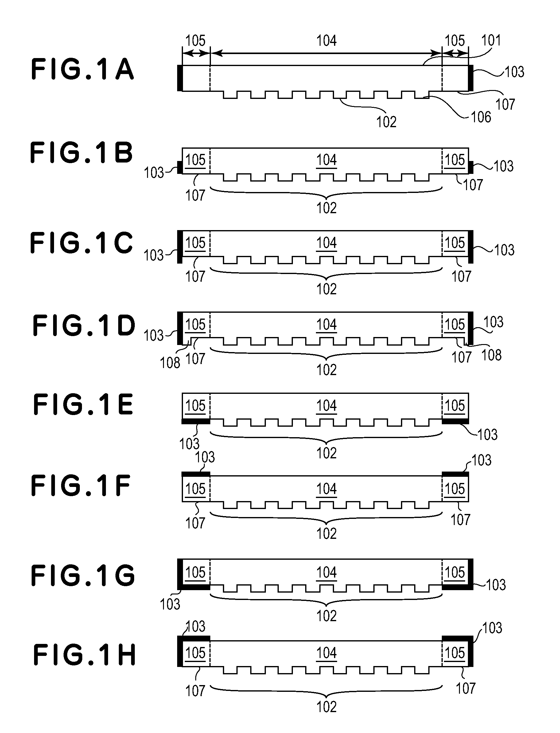
[0039] By the above described light-blocking member, according to the present invention, it is possible to alleviate or suppress the curing of the photocurable resin material in an area other than a portion at which the imprint pattern is to be formed by processing.

Problems solved by technology

By such curing, a large force acts on the mold or the work during release of the mold from the work to damage the mold or the work.
Further, in some cases, the photocurable resin material outside the portion at which the imprint pattern is to be formed is excessively exposed to light passing through the outside of the imprint pattern portion formed in the mold during light exposure, thus deformed in an undesirable shape.

Method used


Image

  • Mold, imprint apparatus, and process for producing structure
  • Mold, imprint apparatus, and process for producing structure
  • Mold, imprint apparatus, and process for producing structure

Examples


embodiment of

(Embodiment of Production Process of Structure)

[0108] A process for producing a structure according to an embodiment of the present invention will be described.

[0109]FIGS. 4A and 4B are schematic views for illustrating a procedure for processing a work, wherein FIG. 4A is a top view and FIG. 4B is a sectional view taken along A-A′ line shown in FIG. 4A.

[0110] Referring to FIGS. 4A and 4B, a reference numeral 401 represents a work, 407 represents a mold, 408 represents a substrate, 409 represents a photocurable resin material, and 410 represent a cured resin material after an imprint pattern is transferred onto it. On an entire lateral side of the mold 407, a light-blocking member 103 is provided. Further, a reference numeral 405 represents a processing path which is a shortest path for processing. In the work 401, numbers 1 to 21 each represents an area per one shot of processing and the processing of work is performed on the order of an increasing number. Further, a reference num...


PUM

PropertyMeasurementUnit
widthsaaaaaaaaaa
widthsaaaaaaaaaa
widthsaaaaaaaaaa

Abstract

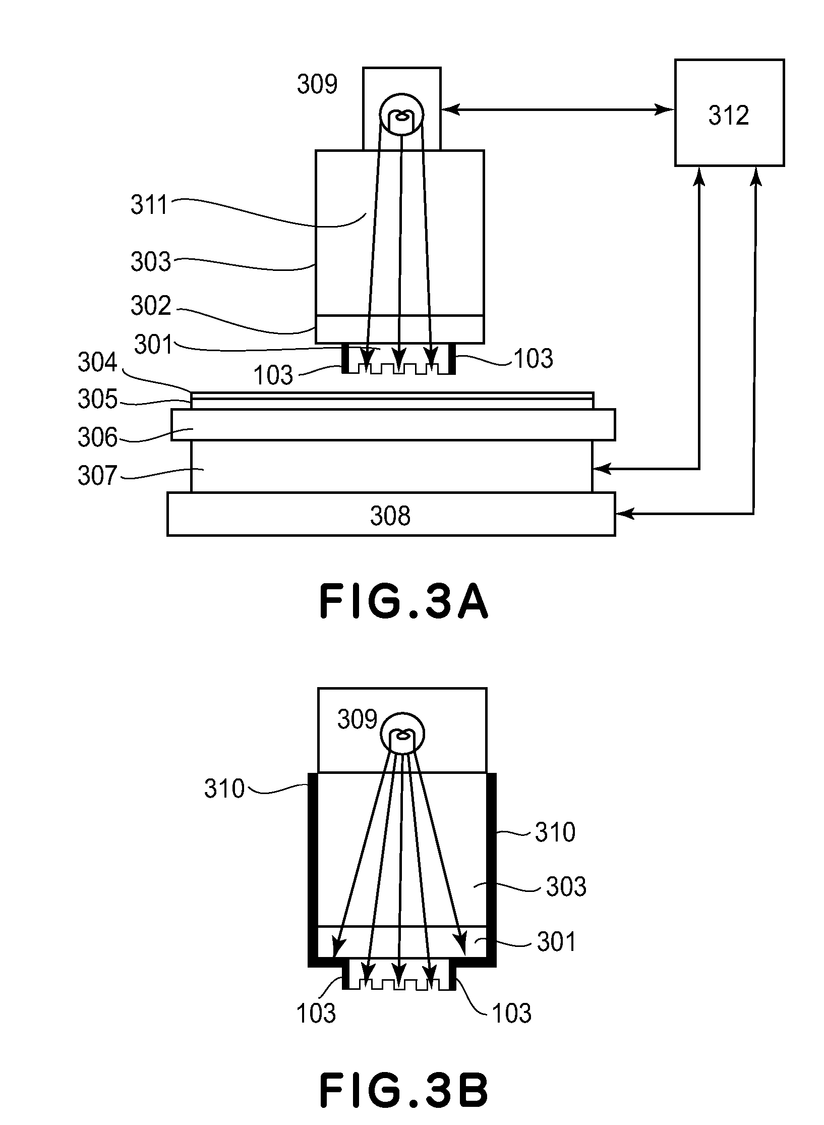
In order to alleviate or suppress curing of a photocurable resin material in an area in which the curing of the photocurable resin material is not intended, exposure of the photocurable resin material to light is suppressed through a non-pattern portion at which a light-blocking member is provided by means of a mold having an imprint pattern portion and the non-pattern portion or is suppressed by disposing a light-blocking member so as not to irradiate the photocurable resin material with light not via the mold.

Description

FIELD OF THE INVENTION AND RELATED ART [0001] The present invention relates to a mold having a shape to be transferred onto a work or workpiece (member to be processed). The present invention also relates to an imprint apparatus and a process for producing a structure. [0002] In recent years, as described in Stephan Y. Chou et al., Appl. Phys. Lett., Vol. 67, Issue 21, pp. 3114-3116 (1995), a fine processing technology for transferring a minute structure on a mold onto a work comprising a semiconductor, glass, resin, metal, etc., has been developed and has received attention. [0003] This technology has a resolution on the order of several nanometers, so that it is called nanoimprint (nanoimprinting) or nanoembossing. Although the nanoimprint has the above described resolution, it is also suitably used for processing members having minimum processing widths of not more than 1 mm, not more than 1 μm, and not more than 100 nm. Further, according to the nanoimprint, it is possible to si...

Claims


Application Information

Patent Timeline
Patent Type & Authority Applications(United States)
IPC IPC(8): B41M5/00B81C99/00
CPCB29C35/0894B29C59/022B29C2035/0827Y10T428/24802B82Y10/00B82Y40/00G03F7/0002B29C2059/023G03F7/2012
Inventor SUEHIRA, NOBUHITOSEKI, JUNICHI
Owner CANON KK
Why Eureka
Try Eureka