Flow through cooling assemblies for conduction-cooled circuit modules

a technology of conduction-cooled circuit modules and cooling assemblies, which is applied in the direction of cooling/ventilation/heating modifications, lighting and heating apparatus, and support structure mounting, etc., can solve the problems of reducing the flexibility of design and incompatible three cooling approaches

Active Publication Date: 2007-03-29
LOCKHEED MARTIN CORP
View PDF32 Cites 47 Cited by
  • Summary
  • Abstract
  • Description
  • Claims
  • Application Information

AI Technical Summary

Benefits of technology

[0010] According to a second aspect of the invention, a circuit module chassis assembly is provided for operation with a conduction-cooled circuit module. The circuit module chassis assembly comprises a chassis including a first sidewall and a second sidewall, a cooling assembly in the chassis, and a cooling fluid source coupled to the cooling assembly. The cooling assembly comprises a housing having a first end engaging the first sidewall of the chassis and a second end engaging

Problems solved by technology

A problem arises in that the three cooling approaches are incompatible in the circuit module chassis assembly.
However, this approach limits the application of the chassis

Method used


Image

  • Flow through cooling assemblies for conduction-cooled circuit modules
  • Flow through cooling assemblies for conduction-cooled circuit modules
  • Flow through cooling assemblies for conduction-cooled circuit modules

Examples


first embodiment

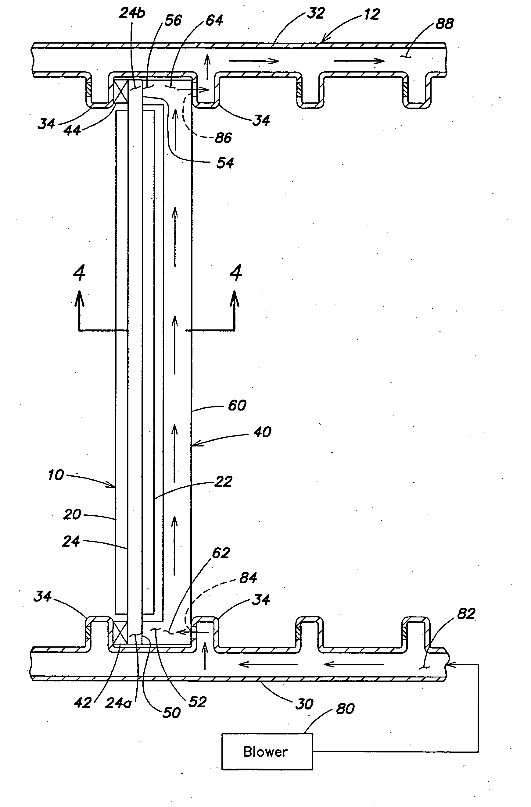
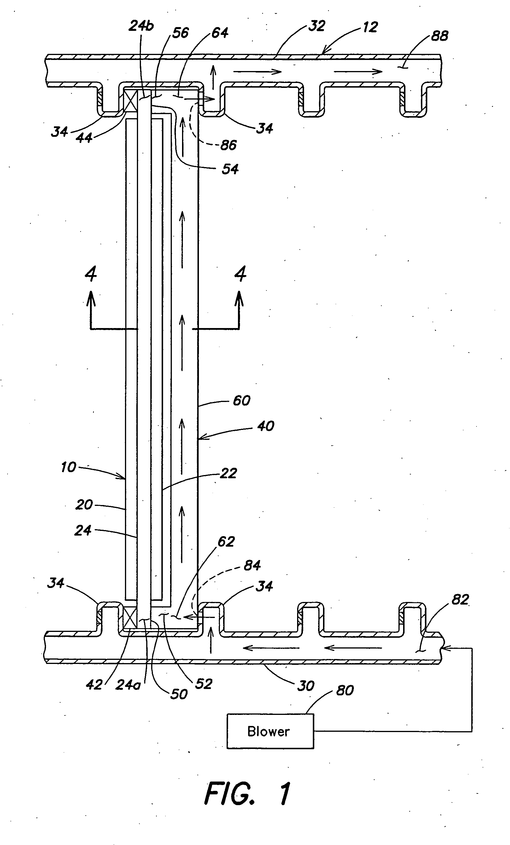
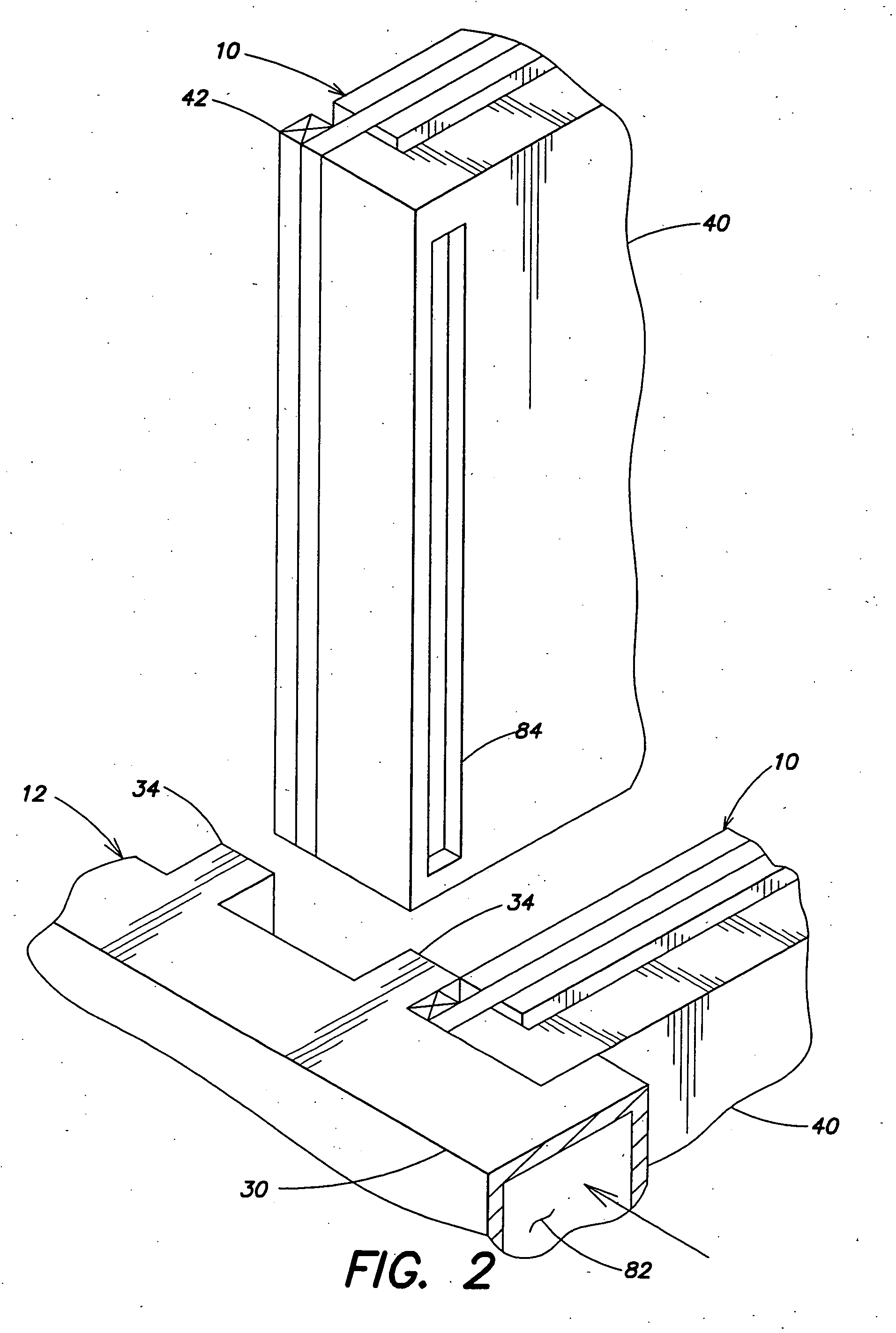
[0020] A circuit module chassis assembly in accordance with the invention shown in FIGS. 1-4. A simplified partial top view of the circuit module chassis assembly is shown in FIG. 1. A conduction-cooled circuit module 10 is mounted in a chassis 12. Chassis 12 may be configured to hold 15 to 20 circuit modules, for example, one of which is shown in FIG. 1.

[0021] Circuit module 10 may include a circuit card 20 and a circuit card 22 mounted to a thermally conductive plate 24, which may be aluminum. Each of circuit cards 20 and 22 may include integrated circuits and other electrical components mounted on a printed wiring board. In various embodiments, circuit module 10 may include circuit card 20, circuit card 22, or both. Each of circuit cards 20 and 22 includes a connector 26 (FIG. 4) for engaging a connector of chassis 12. Thermally conductive plate 24 includes extensions 24a and 24b beyond circuit cards 20 and 22, which define surfaces 50 and 54, respectively, for thermal transfer b...

second embodiment

[0030] A circuit module chassis assembly in accordance with the invention is shown in FIGS. 5 and 6. A simplified partial top view of the circuit module chassis assembly is shown in FIG. 5. Like elements in FIGS. 1-6 have the same reference numerals.

[0031] As in the embodiment of FIGS. 1-4, conduction-cooled circuit module 10 is mounted in chassis 12. Chassis 12 includes first sidewall 30 and second sidewall 32, each of which includes spaced-apart rails 34 that define mounting locations for circuit module 10 and additional circuit modules (not shown).

[0032] The circuit module chassis assembly further includes a liquid-flow-through cooling adapter 140 mounted in chassis 12 in proximity to circuit module 10. Cooling adapter 140 and circuit module 10 are secured between adjacent rails 34 of sidewalls 30 and 32 by mounting hardware in the form of wedge-lock fasteners 42 and 44. Fasteners 42 and 44 establish a pressure connection between circuit module 10, cooling adapter 140, and rails...

third embodiment

[0036] A circuit module chassis assembly in accordance with the invention is shown in FIG. 7. Like elements in FIGS. 1-7 have the same reference numerals.

[0037] As in the embodiment of FIGS. 1-4, conduction-cooled circuit module 10 is mounted in chassis 12. Chassis 12 includes first sidewall 30 and second sidewall 32, each of which includes spaced apart rails 34 that define mounting locations for circuit module 10 and additional circuit modules (not shown).

[0038] The circuit module chassis assembly further includes a cooling assembly 240 in chassis 12 in proximity to circuit module 10. Circuit module 10 is secured between rail 34 and cooling assembly 240 by mounting hardware in the form of wedge lock fasteners 42 and 44. Fasteners 42 and 44 establish a pressure connection between circuit module 10, cooling assembly 240, and rails 34.

[0039] Cooling assembly 240 includes a housing 260 having a first end 262 secured to sidewall 30 and a second end 264 secured to sidewall 32. In the e...


PUM


Abstract

A cooling assembly is located in a chassis with a conduction-cooled circuit module and permits the conduction-cooled circuit module to be utilized in an air-flow-through or liquid-flow-through circuit module chassis assembly. The cooling assembly may be a removable cooling adapter or may be integral with the chassis. The cooling assembly includes a housing having a first end and a second end and defining one or more fluid passages. The housing further includes a thermal contact surface to contact the conduction-cooled circuit module. The cooling assembly may be configured for air-flow-through or liquid-flow-through cooling of the conduction-cooled circuit module.

Description

FIELD OF THE INVENTION [0001] This invention relates to circuit module chassis assemblies wherein circuit modules are mounted in a chassis and, more particularly, to cooling assemblies that permit conduction-cooled circuit modules to be used in circuit module chassis assemblies that are designed for air-flow-through cooling or liquid-flow-through cooling. BACKGROUND OF THE INVENTION [0002] Circuit module chassis assemblies which include multiple circuit modules mounted in a chassis are widely used in electronic applications. A circuit module chassis assembly may include a chassis configured to mechanically support the circuit modules, electrical connectors to interconnect the circuit modules, power supplies for operation of the circuit modules and one or more external connectors to connect the circuit module assembly to external equipment. The circuit module chassis assemblies are widely used in military and aircraft applications, but are not limited to such applications. Circuit mo...

Claims


Application Information

Patent Timeline
IPC IPC(8): H05K7/20
CPCH05K7/20563H05K7/1404
Inventor VOS, DAVID L.STUTZMAN, RANDALL J.LARCHEVEQUE, JONURDA, EUGENE J.
Owner LOCKHEED MARTIN CORP
Why Eureka
Try Eureka