Developer Cartridge, Image Forming Unit And Image Forming Apparatus

a technology of image forming apparatus and developer cartridge, which is applied in the direction of electrographic process apparatus, instruments, optics, etc., can solve the problems of increased cost of image forming unit and printer (i.e., image forming apparatus), leakage of toner outside through, etc., and achieve the effect of preventing leakage of toner during transport and reducing the cost of image forming unit and image forming apparatus

Active Publication Date: 2007-04-05
OKI ELECTRIC IND CO LTD
View PDF8 Cites 16 Cited by
  • Summary
  • Abstract
  • Description
  • Claims
  • Application Information

AI Technical Summary

Benefits of technology

[0009] With such an arrangement, in the manufacturing process, it becomes possible to pack and ship the image forming unit in such a manner that the developer cartridge is mounted to the main body of the image forming unit, with the developer supplying portion being closed. Further, it becomes possible to pack and ship the image forming apparatus in such a manner that the image forming unit is mounted to a main body of the image forming apparatus. Further, the leakage of the toner during transport can be prevented.
[0010] Furthermore, since it is not necessary to individually pack and ship the image forming unit and the developer cartridge, the costs of the image forming unit and the image forming apparatus can be reduced.

Problems solved by technology

However, in the conventional printer, when the image forming unit is packed and shipped in such a manner that the developer cartridge is mounted to the main body of the image forming unit, there is a possibility that the toner may leak outside through a joint portion between the toner cartridge and the main body of the image forming unit during transport.
Accordingly, the image forming unit and the developer cartridge are individually packed and shipped, and therefore costs of the image forming unit and the printer (i.e., the image forming apparatus) increase.

Method used


Image

  • Developer Cartridge, Image Forming Unit And Image Forming Apparatus
  • Developer Cartridge, Image Forming Unit And Image Forming Apparatus
  • Developer Cartridge, Image Forming Unit And Image Forming Apparatus

Examples


first embodiment

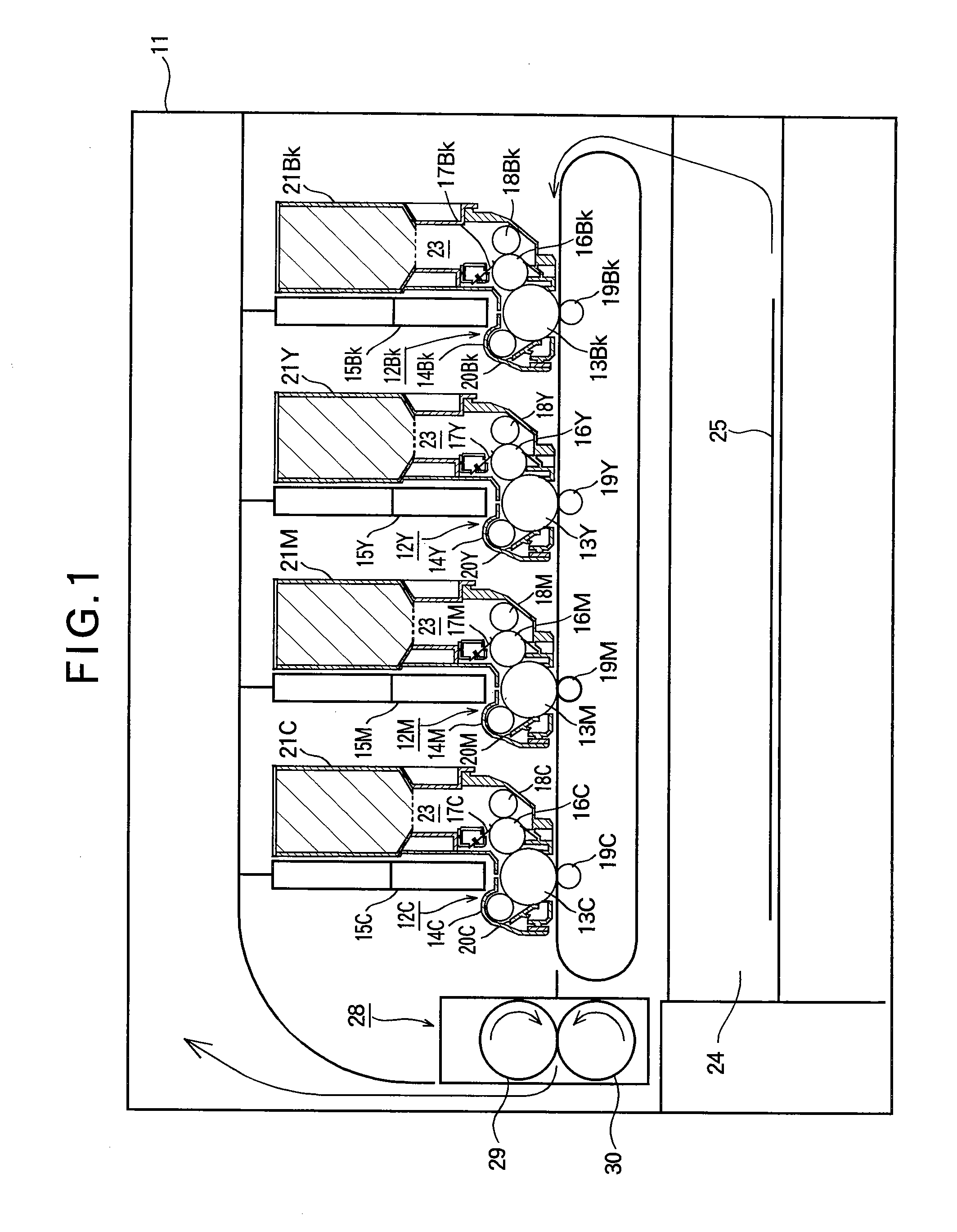
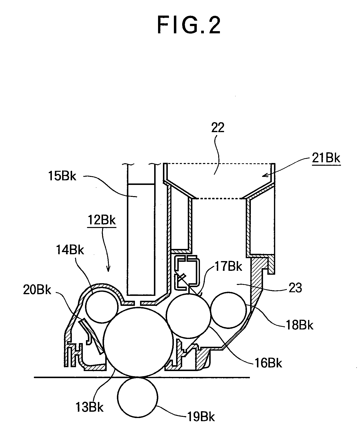
[0040]FIG. 1 is a schematic view of a printer according to the first embodiment of the present invention. FIG. 2 is a sectional view of a main part of the printer according to the first embodiment of the present invention.

[0041] As shown in FIG. 1, a printer 11 includes image forming units 12Bk, 12Y, 12M and 12C (i.e., a plurality of image forming portions). The image forming units 12Bk, 12Y, 12M and 12C are arranged in this order from the upstream side to the downstream side in the feeding direction of a sheet (i.e., a recording medium) 25. The image forming units 12Bk, 12Y, 12M and 12C are configured as LED printing units, and form toner images (i.e., developer images) of black, yellow, magenta and cyan.

[0042] The image forming units 12Bk, 12Y, 12M and 12C include photosensitive drums 13Bk, 13Y, 13M and 13C as image bearing bodies. The image forming units 12Bk, 12Y, 12M and 12C further include charging rollers (i.e., charging devices) 14Bk, 14Y, 14M and 14C provided in oppositio...

second embodiment

[0084] Next, the second embodiment of the present invention will be described. Components having the same structures as those of the first embodiment are assigned the same reference numerals, and the duplicate explanation is omitted. With regard to the advantages obtained by the same structures as those of the first embodiment, the description of the advantages in the first embodiment is incorporated herewith.

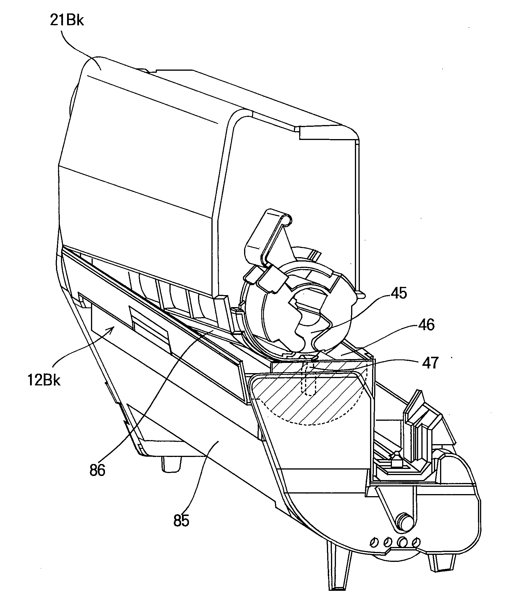
[0085]FIG. 16 is a perspective view of the developer cartridge of the second embodiment of the present invention. FIG. 17 is an exploded perspective view of an inner barrel member of the second embodiment of the present invention.

[0086] In FIG. 16, a developer cartridge 53Bk includes an outer barrel member (i.e., a cassette main body) 56 and an inner barrel member (i.e., an opening-and-closing member) 54. An engaging member (i.e., an engaging portion) 55 is formed on an end of the inner barrel member 54. The outer barrel member 56 includes a toner storing chamber (i.e., a dev...


PUM


Abstract

A developer cartridge includes a developer storing portion in which a developer is stored, a developer supplying portion for supplying the developer to a main body of an image forming unit, an opening-and-closing member that opens and closes the developer supplying portion, an operating member for operating the opening-and-closing member, and an engaging portion engagable with a to-be-engaged portion formed on the main body of the image forming unit. The opening-and-closing member takes one of an opening position where the opening-and-closing member opens the developer supplying portion and a closing position where the opening-and-closing member closes the developer supplying portion, when the engaging portion engages the to-be-engaged portion. The opening-and-closing member takes the closing position where the opening-and-closing member closes the developer supplying portion, when the engaging portion disengages from the to-be-engaged portion.

Description

BACKGROUND OF THE INVENTION [0001] This invention relates to a developer cartridge, an image forming unit and an image forming apparatus. [0002] In a conventional electrophotographic image forming apparatus such as a printer, a copier, a facsimile, a combined machine or the like (for example, a printer), a surface of a photosensitive drum is uniformly charged by a charging roller. The surface of the photosensitive drum is exposed to the light by means of an LED head so that a latent image is formed thereon. The latent image is developed with toner (i.e., developer) that forms a thin layer on a developing roller and adheres to the latent image with static electricity. The developed image (i.e., toner image) is transferred to a recording medium by means of a transferring roller, and is fixed to the recording medium by means of a fixing device. After the transferring, the toner remaining on the photosensitive drum is removed by a cleaning blade. [0003] The above described photosensitiv...

Claims


Application Information

Patent Timeline
Patent Type & Authority Applications(United States)
IPC IPC(8): G03G15/08
CPCG03G2215/067G03G15/0872G03G15/0886G03G15/0875
Inventor OTA, ATSUSHI
Owner OKI ELECTRIC IND CO LTD
Why Eureka
Try Eureka