Cleaning box and method for cleaning pipe by utilizing the same

a cleaning box and pipe technology, applied in the field of cleaning apparatus, can solve the problems of waste materials, easy leakage of sealing, parts of vacuum pipes not covered by heater jackets,

Inactive Publication Date: 2007-04-12
UNITED MICROELECTRONICS CORP
View PDF4 Cites 2 Cited by
  • Summary
  • Abstract
  • Description
  • Claims
  • Application Information

AI Technical Summary

Benefits of technology

[0011] Therefore, it is an objective of the present invention to provide a cleaning box for holding the waste materials in the connection pipe, so as to prevent the waste materials from leaking.

Problems solved by technology

However, parts of the vacuum pipe not covered by the heater jacket will need to be cleaned from time to time.
However, since the plastic bag 120 is easily ripped, using the plastic bag 120 to catch the waste materials 118 may result in security issues, such as: leaking of the waste materials 118 due to the waste materials 118 being dropped outside of the plastic bag 120.
In addition, since the tightness of the plastic bag 120 is poor, that the waste materials 118 easily leaks from the sealing between the plastic bag 120 and the vacuum pipe 102 has significantly negative impacts on health of the operators.
On the other hand, if the dust leaks from the joint sealing between the plastic bag 120 and the vacuum pipe 102, that the sensor detection point of the smoke alarm will rise and the smoke alarm is activated may cause false alarm.

Method used


Image

  • Cleaning box and method for cleaning pipe by utilizing the same
  • Cleaning box and method for cleaning pipe by utilizing the same
  • Cleaning box and method for cleaning pipe by utilizing the same

Examples


Embodiment Construction

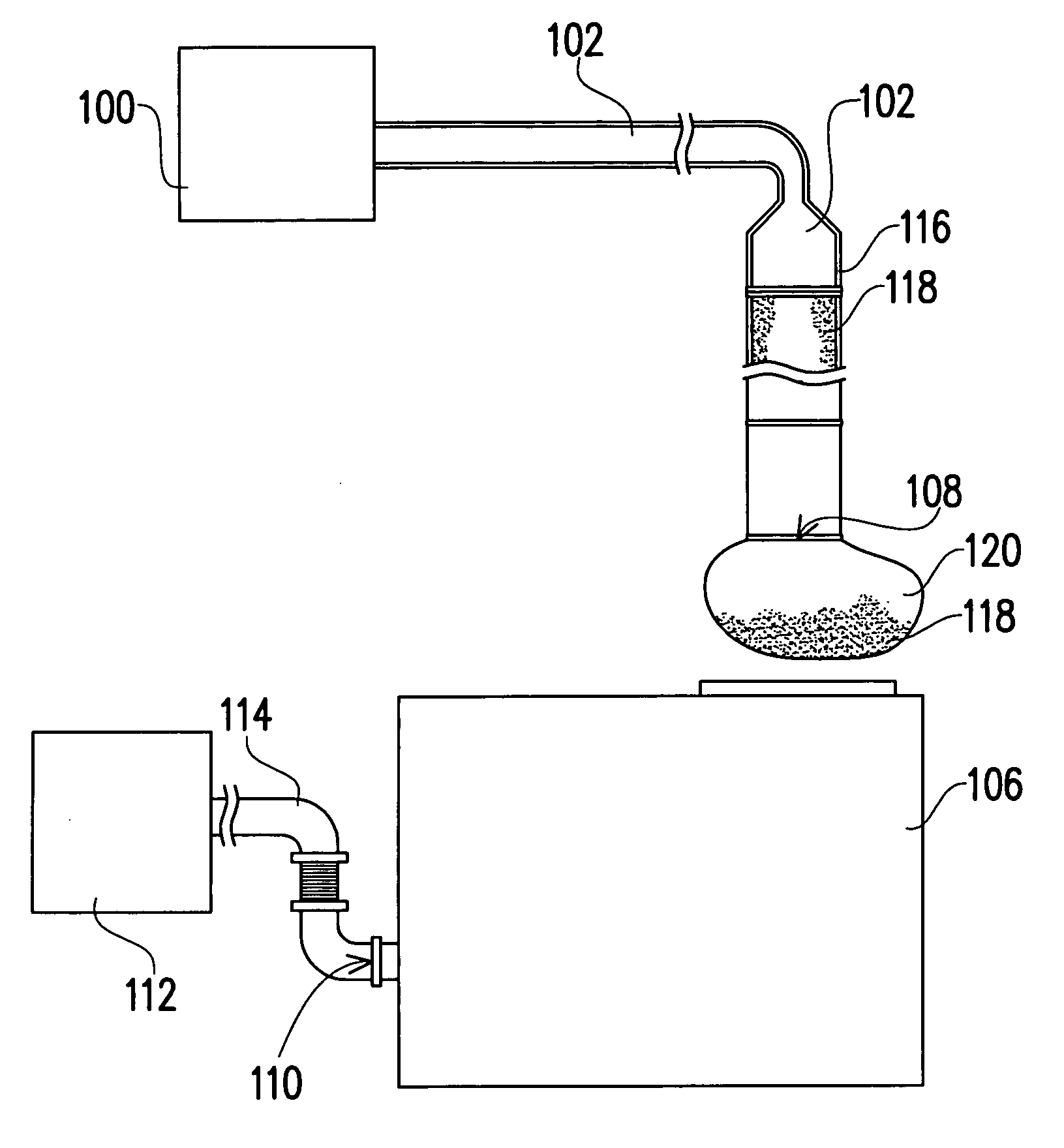
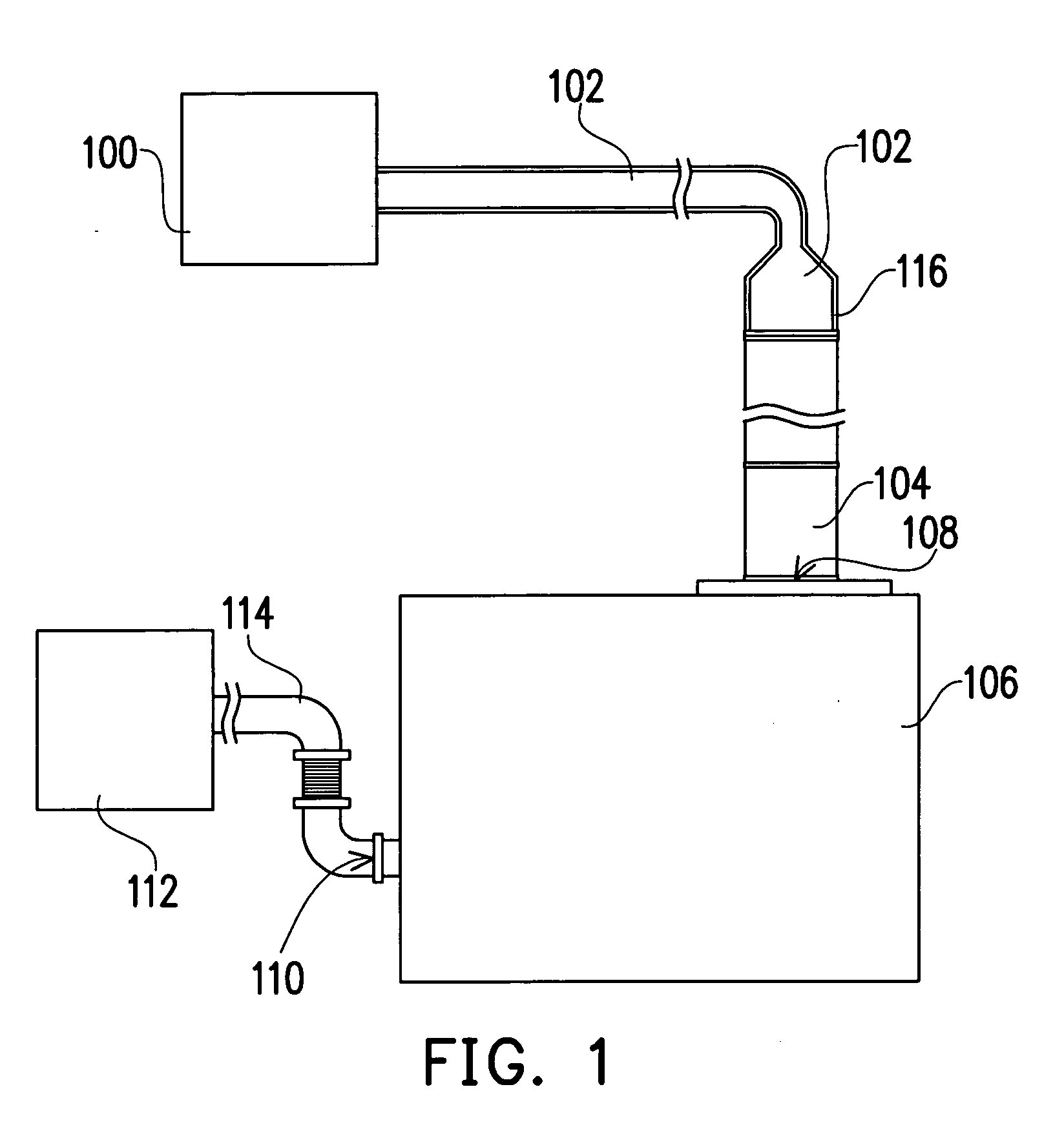
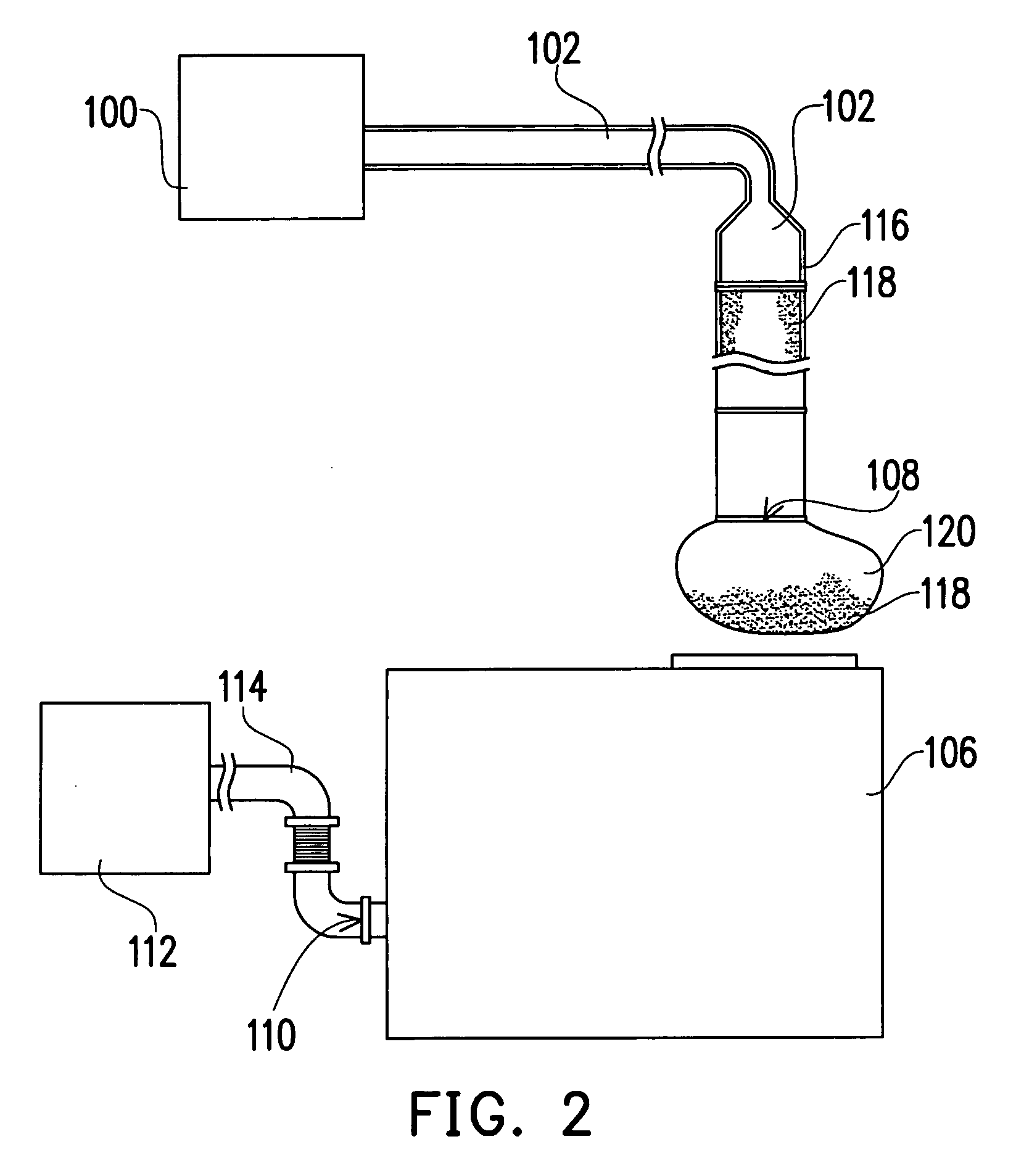
[0032] The method for cleaning pipe provided by the present invention is suitable for cleaning the waste materials on the inner wall of a vacuum pipe in a working machine. The waste materials mentioned above may be adhered to the inner wall of the vacuum pipe, which is not covered by the heater jacket. The cleaning box and the method for cleaning pipe provided by the present invention are described in greater detail hereinafter with reference to an example of cleaning the waste materials in the pipe of a semiconductor fabricating system.

[0033] Referred to FIG. 1, in the present semiconductor fabricating system, a vacuum pump 106 is used by a working machine 100 to generate a vacuum operating environment, and the waste gas exhausted by the vacuum pump 106 is exhausted outside of the semiconductor fabricating system by an exhaust apparatus 112. In this case, the working machine 100 may be a metal etching machine. In addition, the interconnection of the working machine 100, the vacuum...


PUM


Abstract

A cleaning box used to catch the waste materials from a vacuum pipe of a working machine is provided. The present invention is characterized in that the cleaning box includes a catch inlet and an air outlet wherein the catch inlet is connected to the vacuum pipe of the working machine, and the air outlet is connected to an exhaust pipe of an exhaust apparatus. That the cleaning box has high rigidity can prevent the cleaning box from breaking and the waste materials from leaking out of the cleaning box.

Description

BACKGROUND OF THE INVENTION [0001] 1. Field of the Invention [0002] The present invention relates to a cleaning apparatus, and more particularly, to a cleaning box and a method for cleaning pipe by utilizing the same. [0003] 2. Description of the Related Art [0004] According to the characteristics of the manufacturing process, a heater jacket is commonly used in some working machines, such as: the metal etching machine, for adding heat to the vacuum pipe to prevent the waste materials such as polymer from sticking on the inner wall of the vacuum pipe during the semiconductor fabrication. However, parts of the vacuum pipe not covered by the heater jacket will need to be cleaned from time to time. [0005]FIG. 1 schematically shows a connection diagram of a conventional semiconductor fabricating apparatus. FIG. 2 schematically shows a method for cleaning a vacuum pipe of a working machine in the prior art. [0006] Firstly, the interconnection of a working machine 100, a vacuum pump 106, ...

Claims


Application Information

Patent Timeline
Patent Type & Authority Applications(United States)
IPC IPC(8): A47L5/38
CPCB08B9/02B08B17/00
Inventor CHIU, KO-WENWU, CHENG-HSIN
Owner UNITED MICROELECTRONICS CORP
Why Eureka
Try Eureka