
Free weight support device

a support device and weight technology, applied in the direction of muscle exercise devices, sports equipment, gymnastics, etc., can solve the problems of weightlifter fatigue, many weightlifters opting to exercise alone, and weightlifter fatigue more easily during exercis

Inactive Publication Date: 2007-04-12
MURRAY GRANT +1
View PDF8 Cites 22 Cited by
  • Summary
  • Abstract
  • Description
  • Claims
  • Application Information

AI Technical Summary

Benefits of technology

[0015] The subject invention is also directed to an exercise apparatus having a foot member having a bar which is pivotally coupled to the first and second vertical members at a pivot axis. The foot member may also include a stop means for releasably securing the first and second vertical members in the first position and second position. The stop means may be operable between an engaged position and a released po

Problems solved by technology

Unfortunately, the costs associated with retaining the services of skilled trainers can be quite high resulting in many weightlifters opting to exercise alone.
The action of raising the dumbbells before commencing the exercise requires a considerable amount of strength and energy which may cause the weightlifter to fatigue more easily during the exercise.
Often weightlifters will simply drop the dumbbells or barbells which may cause costly damage to the gym floor.
Moreover, given the difficulty associated with raising and balancing dumbbells or barbells without the aid of a “spotter”, the potential for serious injury due to improper technique is very high.
This danger is equally likely among both novice and professional weightlifters.
However, the static positioning of the stands adjacent to the weightlifter interferes with the movement of the weightlifter's arms during the actual performance of the exercise.
This shifting action may cause the weightlifter to lose his grip on the dumbbells or to injure his back.

Method used


Image

  • Free weight support device
  • Free weight support device
  • Free weight support device

Examples


Embodiment Construction

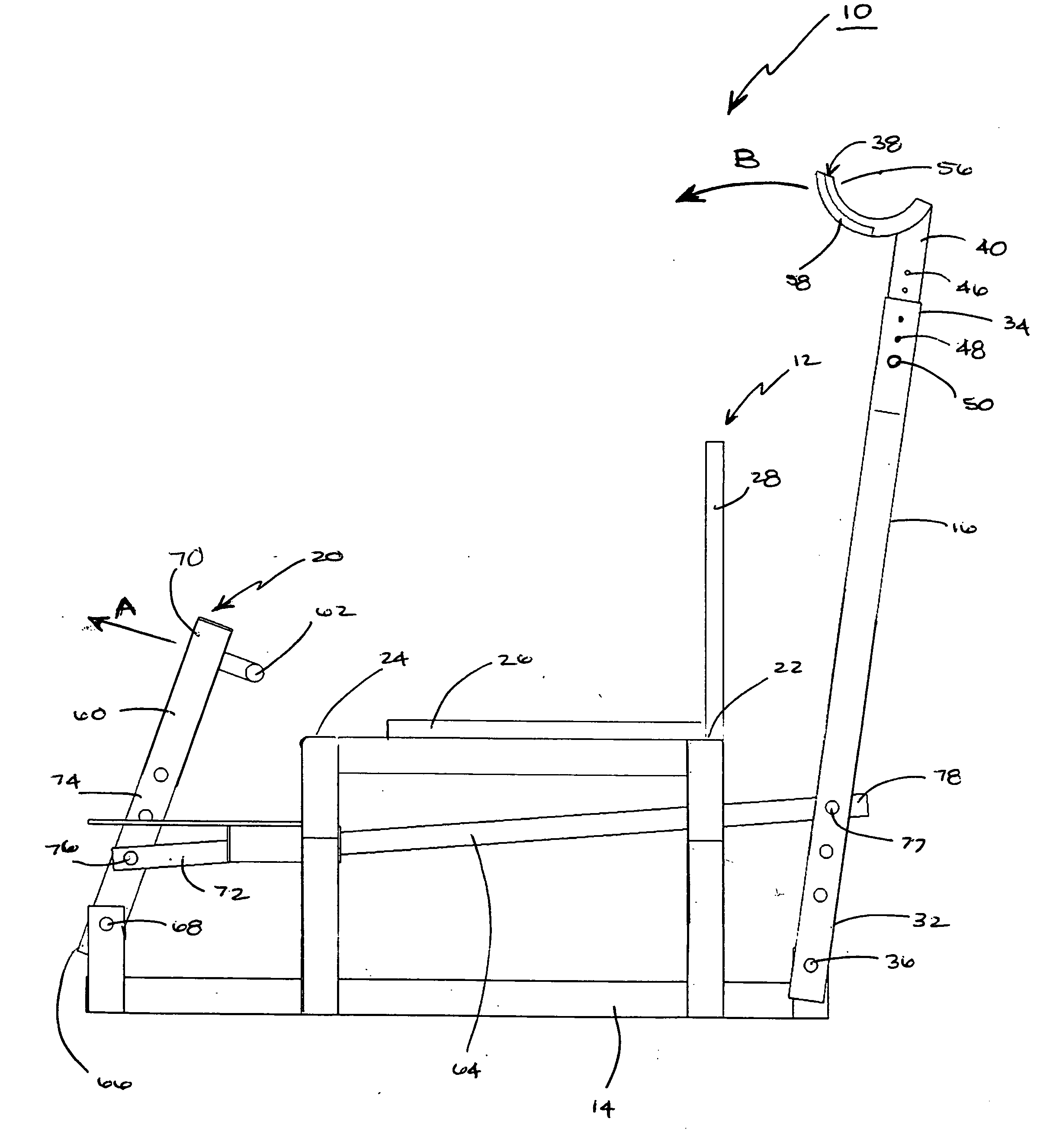
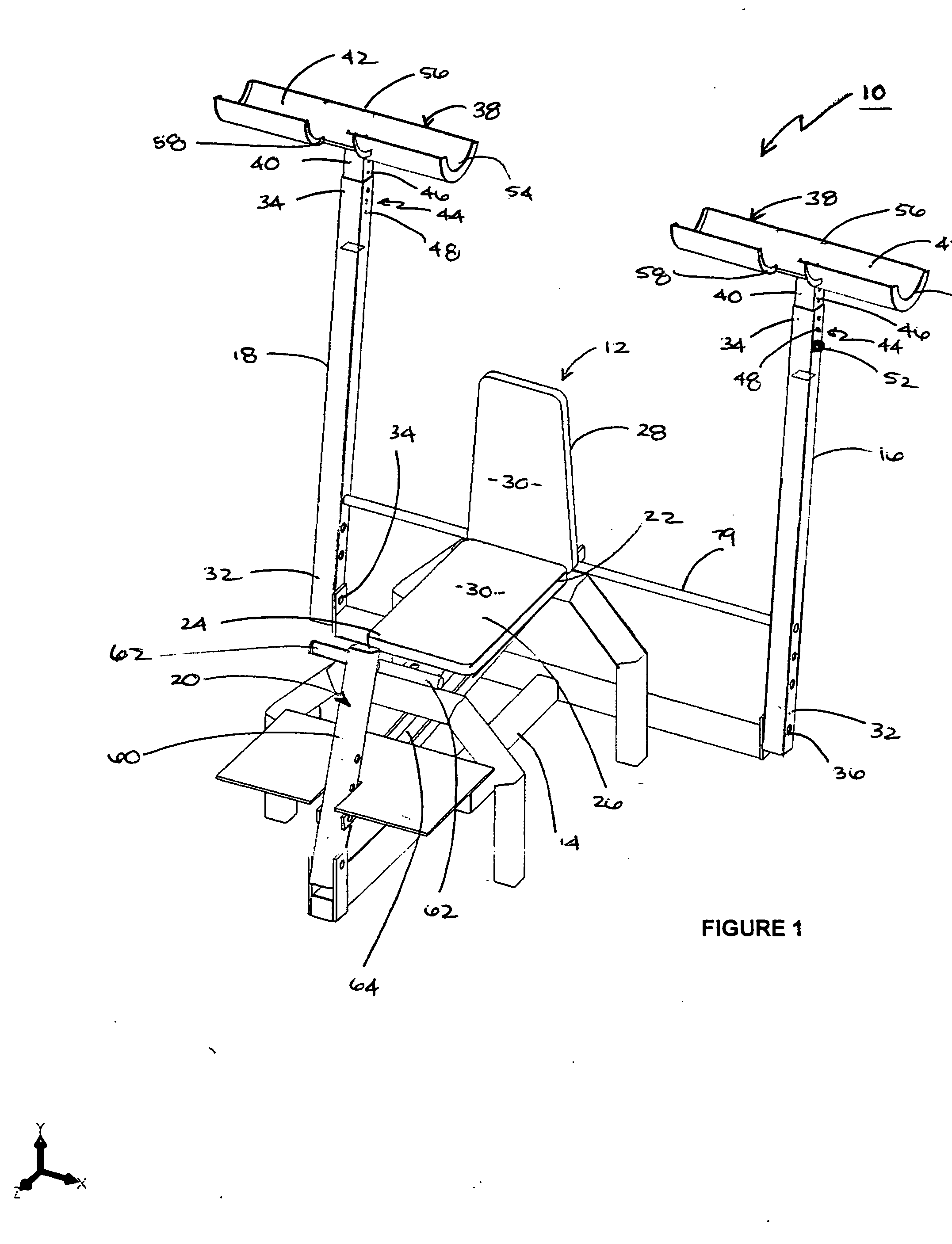
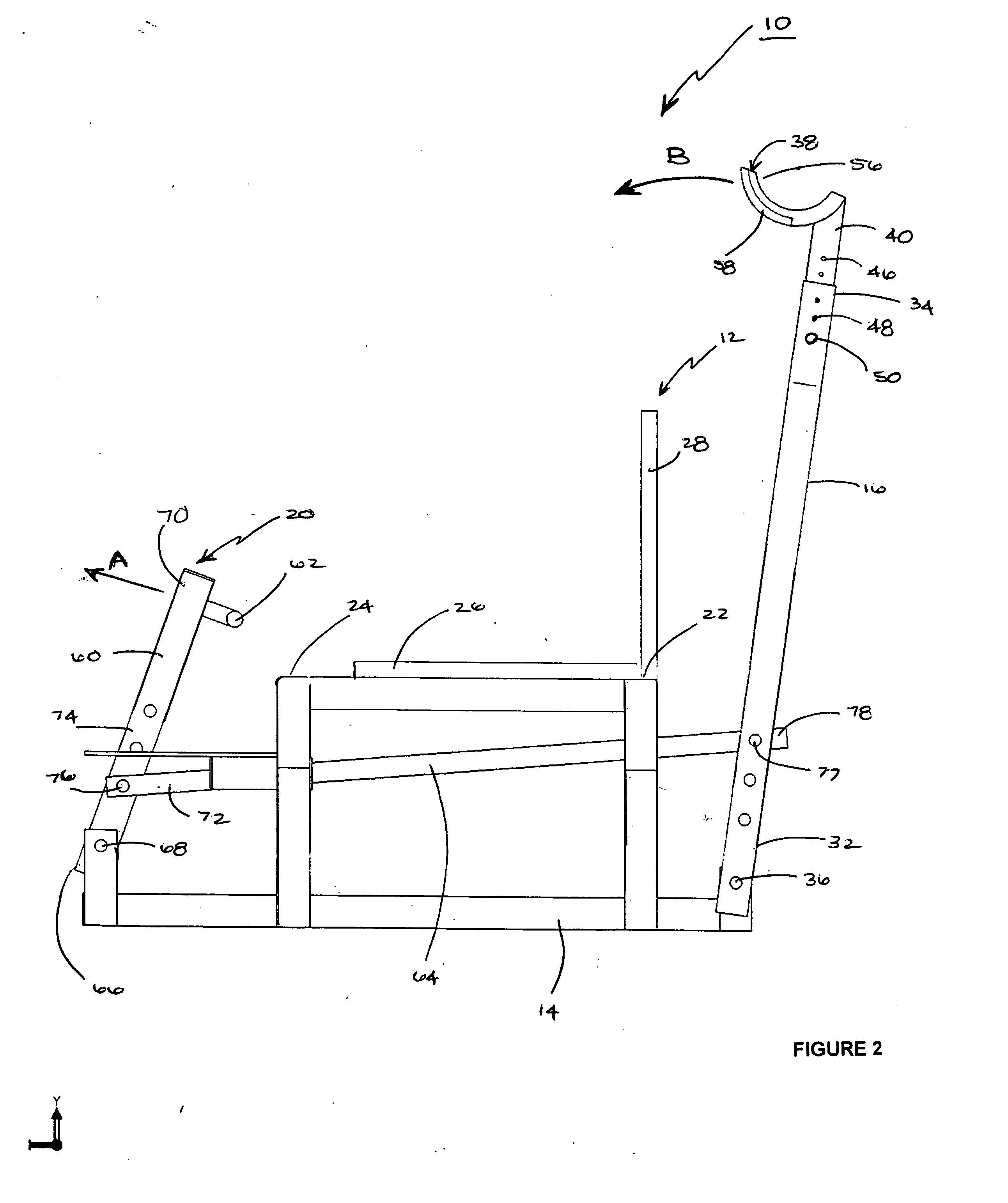
[0025] Reference is made to FIGS. 1, 2 and 3 which illustrate a free weight support device 10 made in accordance with a preferred embodiment of the invention. Free weight support device 10 is positioned adjacent to an exercise bench 12. Free weight support device 10 comprises a base 14, a first vertical member 16 and a second vertical member 18 positioned on opposite sides of bench 12, and a foot member 20 pivotally coupled to the first and second vertical members 16 and 18, respectively. Base 14 is adapted to stably support the first and second vertical members 16 and 18 and the foot member 20 on the floor.

[0026] Referring to the preferred embodiment of the free weight support device 10 shown in FIG. 1, the first and second vertical members 16 and 18 are positioned generally proximate to a back end 22 of exercise bench 12. The foot member 20 is positioned generally proximate to a front end 24 of exercise bench 12. The exercise bench 12 may include a seat portion 26 and a back port...


PUM


Abstract

A free weight support device for use with an exercise bench that is pivotally positionable between a first and second position, and having a base, first and second vertical members pivotally coupled to the base and positioned on opposite sides of the bench, and a foot member coupled to the first and second vertical members and operable by one or more feet of the weightlifter. The foot member being proximate to a front end of the bench and pivotally coupled to the base for pivotally adjusting the position of the first and second vertical members between a first position and a second position. When adjusted into the first position, the first and second vertical members are positioned generally vertically to support the weight of the free weights away from the weightlifter's arms. When adjusted into the second position, the first and second vertical members are pivotally positioned to permit the weightlifter to retrieve the free weights. The first and second vertical members include weight supports having notches to permit the retrieval and replacement of the free weight by the weightlifter.

Description

FIELD OF THE INVENTION [0001] The present invention relates to the field of free weight support devices, and more particularly to free weight support devices that pivotally retract to enable a weightlifter to perform strength training. BACKGROUND OF THE INVENTION [0002] Strength training using free weights or other forms of resistance is an important aspect of a complete physical fitness regime. Physiologically, the benefits of strength training using weights include an increase in muscle size and tone, increased muscle strength, and increases in tendon, bone, and ligament strength. Moreover, strength-training has also been shown to improve psychological health as well, by increasing self-esteem, confidence and self-worth. [0003] When beginning an intensive exercise regime, many people retain the services of a skilled trainer to learn the proper techniques for utilizing the various dumbbells, barbells and other weightlifting equipment in a conventional gym facility. The term “dumbbe...

Claims


Application Information

Patent Timeline
IPC IPC(8): A63B21/078
CPCA63B21/078A63B2021/0783A63B21/1457A63B21/0783A63B21/4029
Inventor MURRAY, GRANTVAN NIEKERK, HUBERT
Owner MURRAY GRANT
Learn More