Joining member having pivotal components for net support structure

a technology of pivotal components and net support structures, which is applied in the direction of ski bindings, water skis, skiing, etc., can solve the problems of sleeve type connecting devices that are not reliable, patents suffer from couple, and net support structures tend to deform

Inactive Publication Date: 2007-04-19
LIN CHIN WU
View PDF5 Cites 38 Cited by
  • Summary
  • Abstract
  • Description
  • Claims
  • Application Information

AI Technical Summary

Benefits of technology

[0007] It is therefore an object of the present invention to provide a net support structure comprising two pairs of leg members; two uprights; two joining members each including two opposite grooves each pivotably secured to the leg member, a transverse socket, and a longitudinal channel adapted to pivotably secure to the upright; a hollow cross member including a hollow, staged plug formed of an elastomeric material, the plug including an internal shoulder and having one end fastened in the socket, two end modules each having an end recess with the other end of the plug fastened therein, and a staged intermediate module including an extension at either end having a diameter smaller than that of the intermediate module, the extension being inserted into a corresponding end of either end module for fastening; an elastic cord passed through the cross member and having either end tied as an enlargement secured to the shoulder of the plug; two disc-shaped members each disposed proximate either end of the cross member and including a central hole with the cross member passed through, and a plurality of peripheral grooves for securing to the leg members and the upright in a folded state of the joining member; and a net including two side sheaths sleeved on the uprights.

Problems solved by technology

However, the patent suffered from a couple of disadvantages.
However, such sleeve type connecting devices are not reliable (i.e., structurally weak).
Thus, the net support structure tends to deform after a period time of use.
However, the Taiwanese patent suffered from a disadvantage.
For example, it is assembly or disassembly is a time consuming process involving steps of insertion or pulling out and other steps.

Method used


Image

  • Joining member having pivotal components for net support structure
  • Joining member having pivotal components for net support structure
  • Joining member having pivotal components for net support structure

Examples


Embodiment Construction

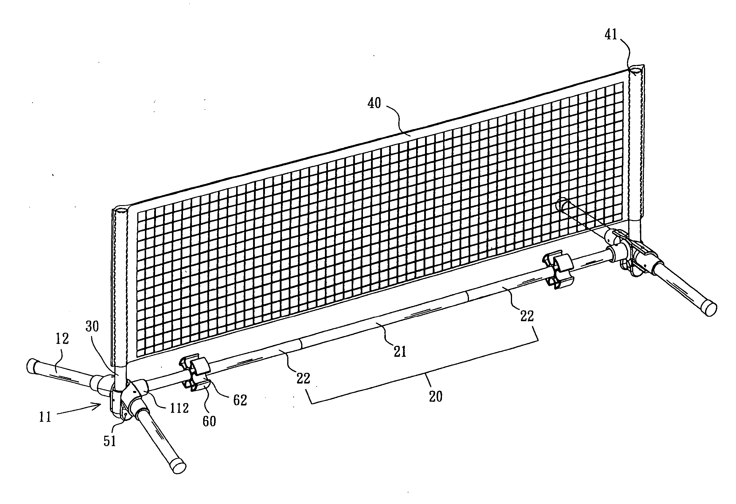
[0019] Referring to FIGS. 3 to 7, a net support structure in accordance with a first preferred embodiment of the invention comprises two leg devices 10, a cross member 20, two uprights 30, and a net 40. Each component is discussed in detailed below.

[0020] The leg device 10 comprises a substantially T-shaped joining member 11 including two opposite grooves 111 of U-section, a transverse socket 112, a longitudinal channel 113 having two opposite slightly projected detents 114 on its inner surface, the channel 113 being adapted to pivotably secure to the upright 30 by driving a pivot 51 through lower apertures thereof and a lower through hole 301 of the upright 30 with the detents 114 matingly engaged with corresponding members (not shown) of the upright 30; and two leg members 12 each adapted to connect to the groove 111 and pivotably secured thereto by driving a pivot 51 through apertures thereof and an end through hole of the leg member 12.

[0021] The hollow cross member 20 compris...


PUM


Abstract

Provided is a net support structure comprising two pairs of leg members; two uprights; two joining members each including two opposite grooves pivotably secured to the leg members, a transverse socket, and a longitudinal channel pivotably secured to the upright; a hollow, multi-segment cross member, a hollow, staged flexible plug including an internal shoulder and having one end fastened in the socket and the other end fastened in either end of the cross member; an elastic cord passed through the cross member and having either end tied as an enlargement secured to the shoulder; two disc-shaped members each disposed proximate either end of the cross member and including a central hole with the cross member passed through, and peripheral grooves for securing to the leg members and the upright when the joining member is folded; and a net including two side sheaths sleeved on the uprights.

Description

BACKGROUND OF THE INVENTION [0001] 1. Field of Invention [0002] The present invention relates to net support structures and more particularly to such a net support structure for supporting badminton net, tennis net, volleyball net, or the like having two joining members having a plurality of (e.g., three) pivotal components (e.g., sockets or the like). [0003] 2. Related Art [0004] Portable net supports for badminton net, tennis net, or the like are gradually gaining popularity, particularly in urban areas by virtue of its easy setting up capability. For example, U.S. Pat. No. 5,816,956 discloses a net support structure as shown in FIG. 1. The net support structure 94 comprises a pair of uprights 92 having two modules 941 interconnected by sleeves, two leg members 95, a cross member 94 having two end modules 942 and an intermediate module 943 interconnected the end modules 942 by sleeves, two joining members 93 each for joining the lower module 941 of the upright 92, the leg member 9...

Claims


Application Information

Patent Timeline
Patent Type & Authority Applications(United States)
IPC IPC(8): A63C19/06A63B61/02A63B61/00
CPCA63B61/003A63B61/02A63B67/18A63B2210/52
Inventor LIN, CHIN-WU
Owner LIN CHIN WU
Why Eureka
Try Eureka