
Pump assembly for an emergency eyewash station

a pump assembly and eyewash technology, applied in the direction of piston pumps, non-positive displacement fluid engines, physical therapy, etc., can solve the problems of inability to maintain a constant and steady flow of eyewash fluid from the dispensing head of the station, and the disadvantage of relying on ordinary tap water as the cleansing agent, etc., to achieve the effect of constant steady flow of eyewash fluid

Inactive Publication Date: 2007-04-26
HONEYWELL SAFETY PROD USA INC
View PDF82 Cites 19 Cited by
  • Summary
  • Abstract
  • Description
  • Claims
  • Application Information

AI Technical Summary

Benefits of technology

[0015] In one embodiment, the drive mechanism comprises a second impeller wheel driven by a source of moving fluid, such as running water. This embodiment utilizes the available source of tap water as a drive mechanism to pump the sterile fluid from the source to the spray nozzles, obviating the need for any electrical power source or complicated gravity feed systems to move the sterile fluid.
[0021] Yet, another object of the present invention is the provision for an impeller assembly for an emergency eyewash station that maintains a constant steady flow of eyewash fluid.

Problems solved by technology

Although plumbed eyewash stations generally provide instant availability of a washing spray they suffer from the disadvantage of relying on ordinary tap water as the cleansing agent.
For example, tap water may carry bacteria and other unknown chemicals and contaminants that could cause infection of the eyes.
Although the force of gravity offers several other advantages, it lacks the advantage of being able to maintain a constant and steady flow of eyewash fluid from the dispensing head of the station.
In fact, the pressure steadily dwindles as the reservoir empties.
However, newer ANSI and OSHA regulations have created additional issues that will need to be addressed, and will require improvements to the existing designs to maintain compliance.

Method used


Image

  • Pump assembly for an emergency eyewash station
  • Pump assembly for an emergency eyewash station
  • Pump assembly for an emergency eyewash station

Examples


Embodiment Construction

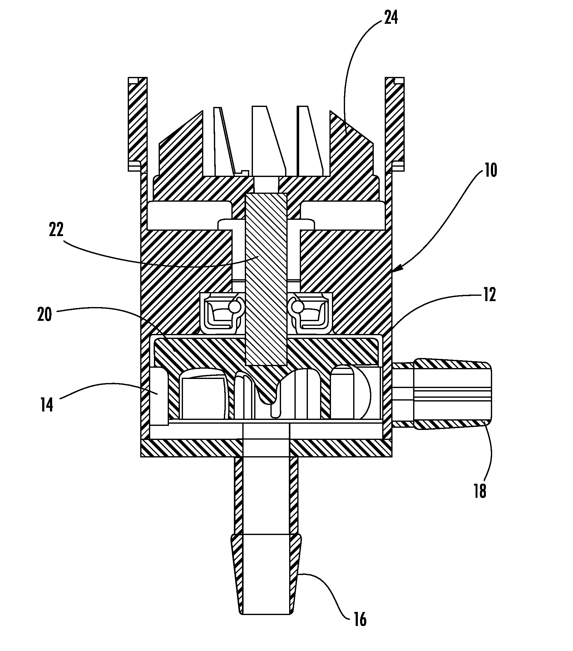
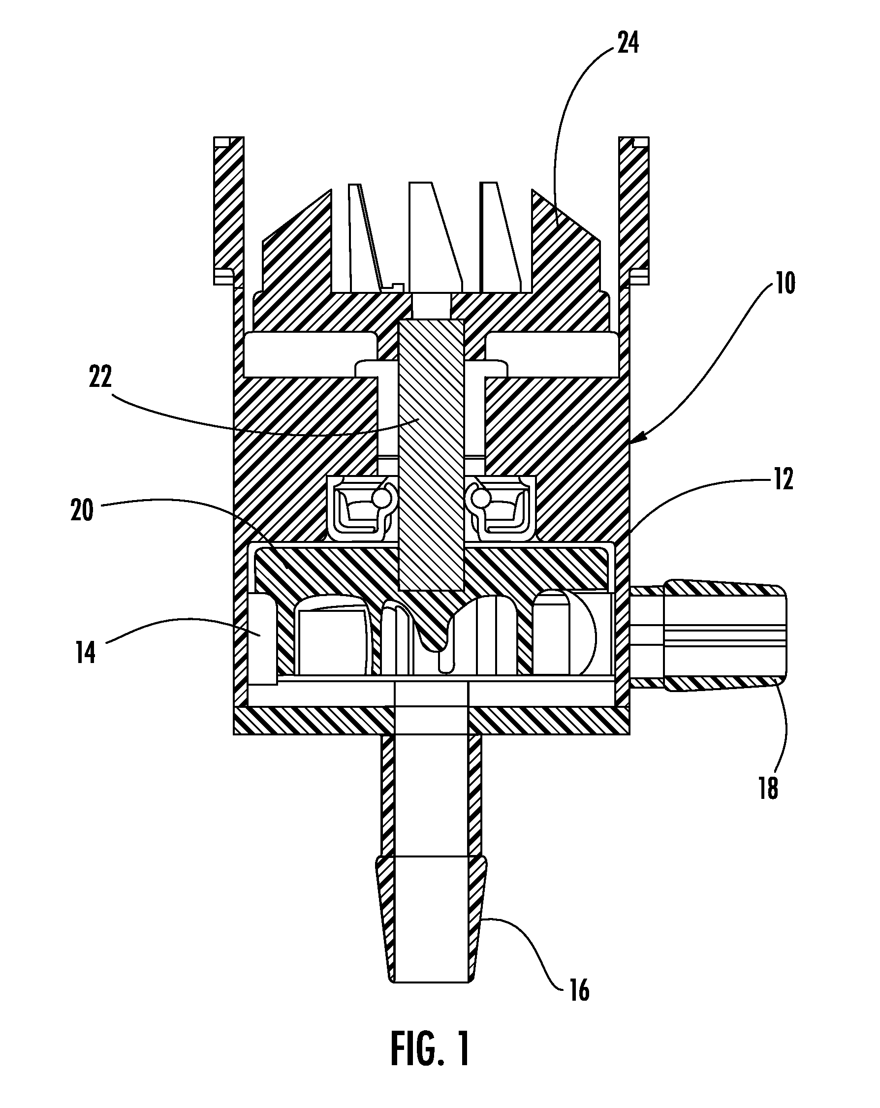
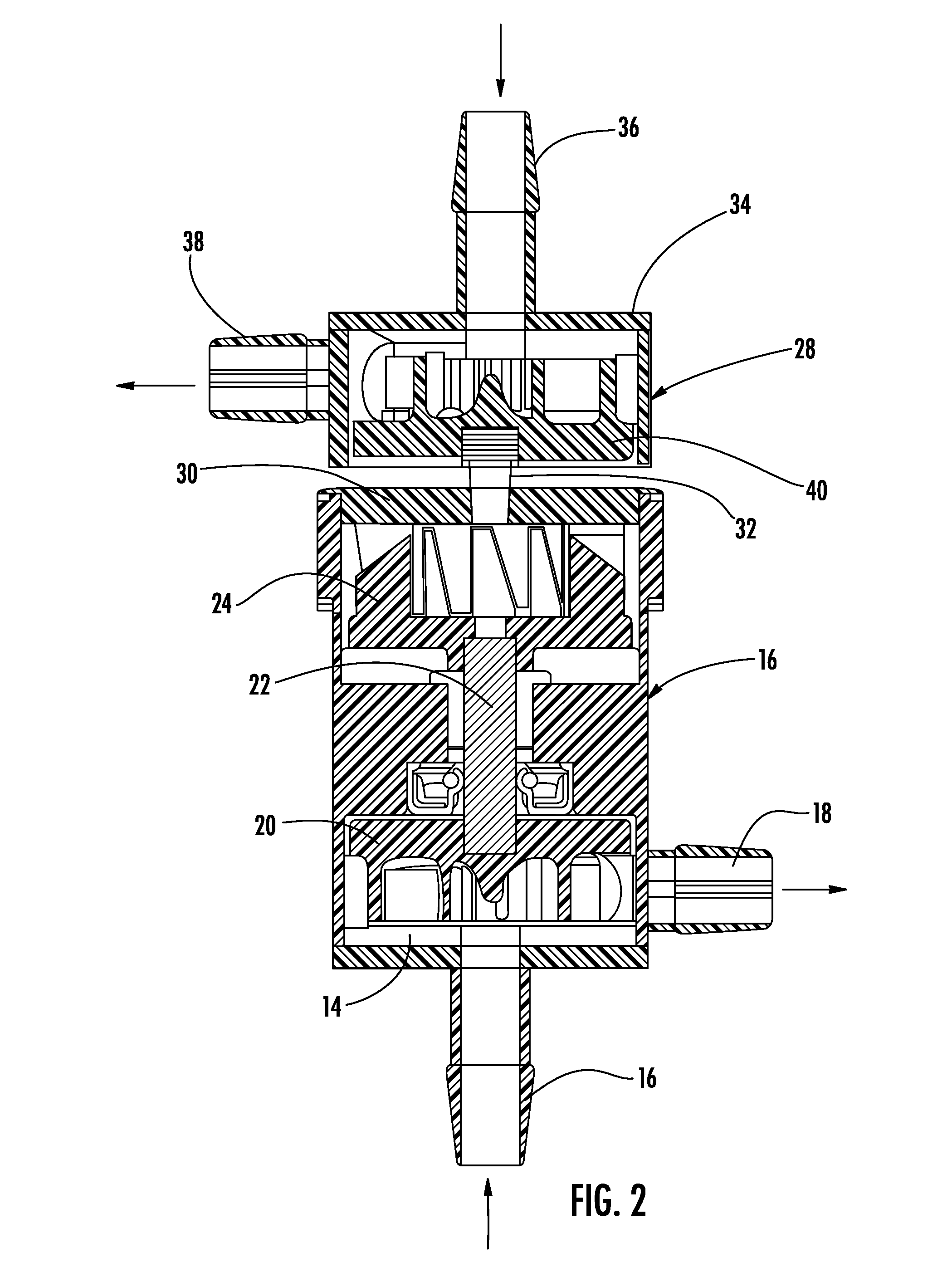
[0030] Referring to FIG. 1, the impeller assembly of the present invention is shown generally at 10. The impeller assembly includes a pump housing 12 having an interior pumping chamber 14, input port 16 into the chamber 14 and an output port 18 out of the chamber 14, and an impeller pump wheel 20 rotatably mounted within the housing 12.

[0031] The impeller pump wheel 20 includes a pump drive shaft 22 having a drive interface 24 that can mate with any one of multiple different drive mechanisms depending upon the installation and application. The impeller pump housing 12 and impeller pump wheel 20 are designed to deliver the recommended 0.4 gallons per minute of fluid to the station spray nozzle (shown in FIG. 3). The impeller assembly 10 is intended to be manufactured from a plastic material and is sterilized prior to installation so that the path through the impeller pump housing 12 remains sterile prior to receiving the sterile eyewash fluid at the time of delivery.

[0032] Referrin...


PUM

PropertyMeasurementUnit
Poweraaaaaaaaaa
Sterileaaaaaaaaaa

Abstract

A pump assembly for an emergency eyewash station and method of retrofitting a plumbed emergency eyewash station is disclosed. The pump is configured into two parts, an impeller assembly and a drive assembly, that are configured to couple together. The impeller assembly is isolated from the drive assembly and can be easily replaced to ensure a sterile fluid path is maintained for the eyewash fluid. The drive assembly can be fluid powered or an electric motor as desired. The present invention allows a plumbed eyewash station to be retrofitted to use a sterile eyewash fluid. The present invention can also be used in portable eyewash station units too.

Description

CROSS-REFERENCE TO RELATED APPLICATION [0001] The present application claims priority to earlier filed U.S. Provisional Patent Application No. 60 / 729,526, filed Oct. 24, 2005, the contents of which are incorporated herein by reference.BACKGROUND OF THE INVENTION [0002] 1. Field of the Invention [0003] The present invention relates generally to emergency eyewash stations, and more particularly to an impeller assembly for such stations. [0004] 2. Background of the Related Art [0005] Emergency eyewash stations take many forms, including plumbed stations, self-contained fixed-mounted units and portable units. Generally speaking, these stations are designed to dispense eyewash fluid (typically water) upon demand. [0006] The plumbed eyewash stations are generally connected to the water supply pipes of an existing sink or are installed as a stand-alone emergency eyewash station with the water supply and draining connected to the regular building water systems. An example of a plumbed eyewa...

Claims


Application Information

Patent Timeline
IPC IPC(8): A61H33/00A61H33/04
CPCA61H35/02A61H2201/1238Y10T29/49238Y10T29/49716F04D25/02
Inventor DEVINAT, BENOITCOPELAND, DAVID J.PEREIRA, MICHAEL C.
Owner HONEYWELL SAFETY PROD USA INC
Learn More