Electric machine

Inactive Publication Date: 2007-05-03
CATERPILLAR INC
View PDF94 Cites 29 Cited by
  • Summary
  • Abstract
  • Description
  • Claims
  • Application Information

AI Technical Summary

Benefits of technology

[0007] One disclosed embodiment relates to an electric machine that may include a stator and a rotor disposed adjacent the stator. The rotor may be rotatable around a rotor rotation axis. The rotor may include a rotor core and a plurality of permanent magnets. The plurality of permanent magnets may include a permanent-magnet cluster disposed at least partially within the rotor core. The permanent-magnet cluster may be configured to create a magnetic pole of the rotor. Additionally, the permanent-magnet cluster may include multiple radial permanent-magnet layers. The rotor may also include one or more axially-extending channels located in a portion of the rotor core disposed between adjacent radial permanent-magnet layers.
[0008] Another aspect of the present disclosure relates to an electric machine that may include a stator and a rotor disposed adjacent the stator. The rotor may be rotatable around a rotor rotation axis. The rotor may include a rotor core and a plurality of permanent magnets mounted to the rotor core. The plurality of permanent magnets may create a plurality of magnetic poles of the rotor. Additionally, the rotor may include one or more axially-extending channels disposed within the rotor core. At least one of the axi

Problems solved by technology

A permanent-magnet type rotor having only a single permanent magnet creating each of its magnetic poles may, however, limit the performance potential of the associated electric machine.
For example, portions of the rotor core between the layers of permanent magnets have relatively large masses, which may cause relatively large centrifugal forces on these portions of the rotor core during rotation of the rotor.
This may create undesirably high stresses in the relatively narrow portions of the rotor core that connect the portions of the rotor core between the layers of magnets to the portions of the rotor core disposed radially inside the inner layer of magnets.
This may cause the permanent magnets to reach undesirably high temperatures.

Method used


Image

  • Electric machine
  • Electric machine
  • Electric machine

Examples


Embodiment Construction

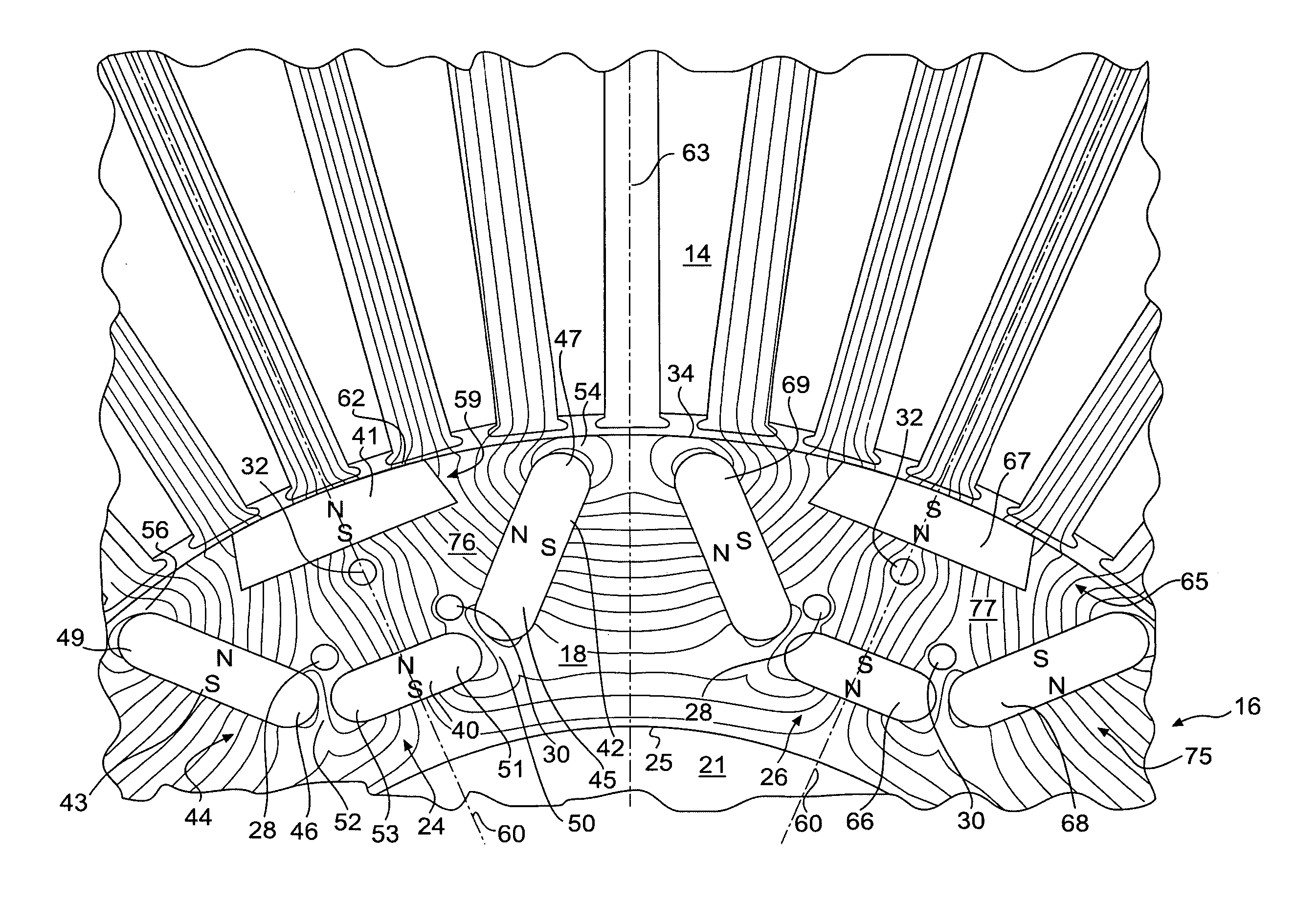
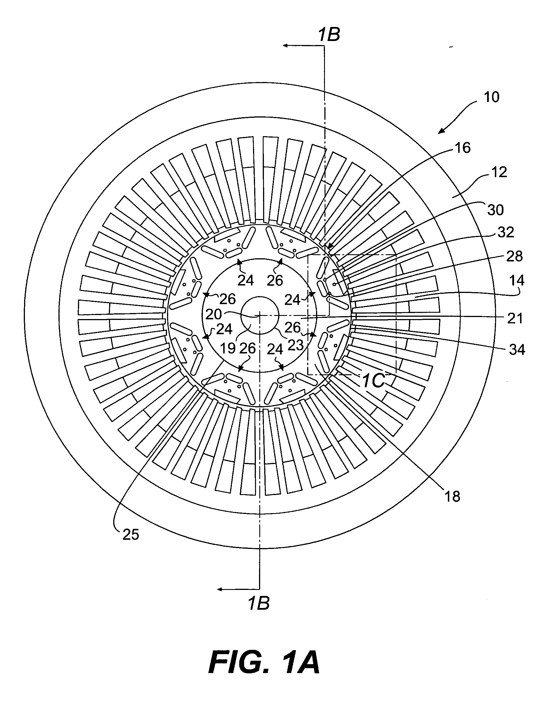
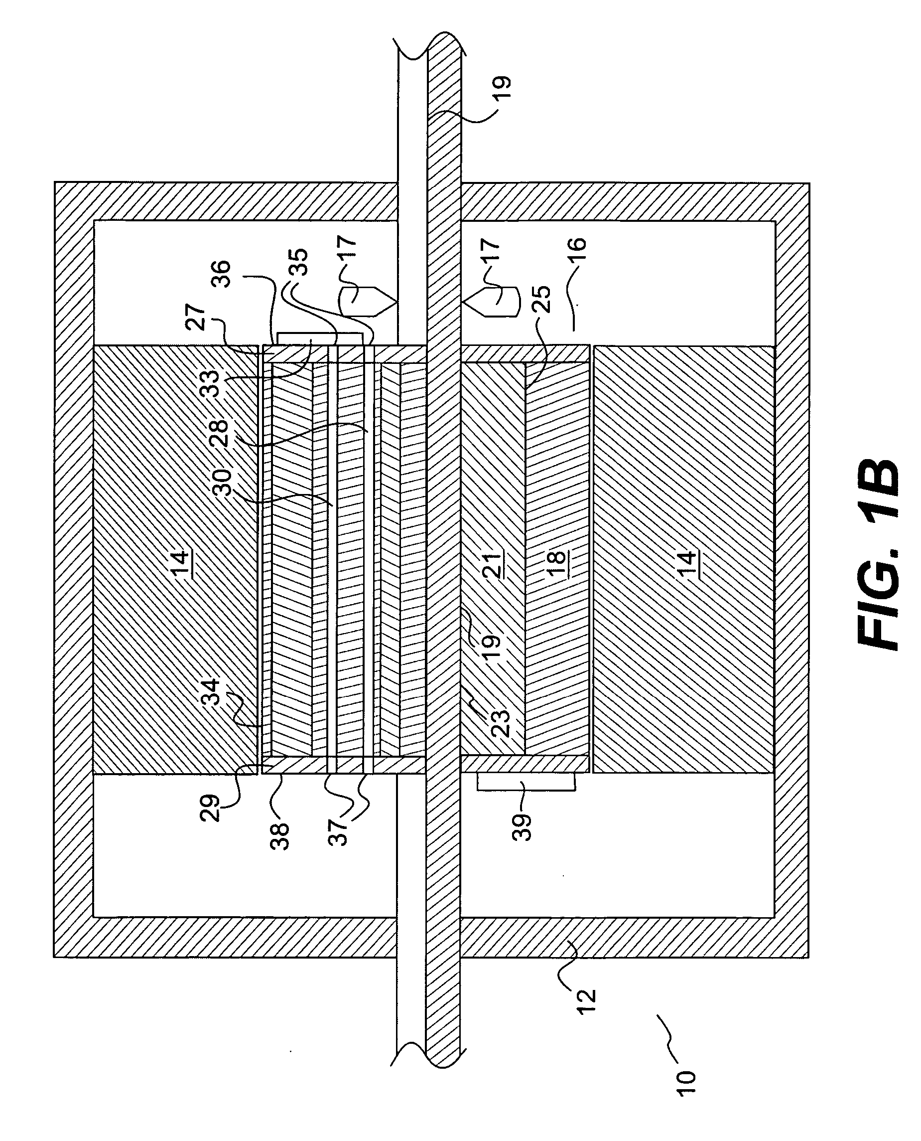
[0013]FIGS. 1A and 1B illustrate one embodiment of an electric machine 10 according to the present disclosure. Electric machine 10 may include a housing 12, a stator 14, rotor 16. Electric machine 10 may be configured to operate as an electric motor and / or an electric generator.

[0014] Housing 12 may provide support for stator 14 and rotor 16. Rotor 16 may be supported by housing 12 in such a manner that rotor 16 may rotate about a rotor rotation axis 20. Housing 12 may support stator 14 in a stationary position adjacent rotor 16. As FIG. 1A shows, in some embodiments, stator 14 may extend around rotor rotation axis 20 and rotor 16.

[0015] Stator 14 may include windings of an electrical conductor (not shown), such as wire. In some embodiments, such windings of the electrical conductor may be configured to receive electricity from an electrical power source and produce a rotating magnetic field. Additionally, in some embodiments, such coils of electrical conductor may be configured t...


PUM


Abstract

An electric machine includes a stator and a rotor disposed adjacent the stator. The rotor may be rotatable around a rotor rotation axis. The rotor may include a rotor core and a plurality of permanent magnets. The plurality of permanent magnets may include a permanent-magnet cluster disposed at least partially within the rotor core. The permanent-magnet cluster may be configured to create a magnetic pole of the rotor. Additionally, the permanent-magnet cluster may include multiple radial permanent-magnet layers. The rotor may also include one or more axially-extending channels located in a portion of the rotor core disposed between adjacent radial permanent-magnet layers.

Description

TECHNICAL FIELD [0001] The present disclosure relates to electric machines having a stator and a rotor and, more particularly, to electric machines having a rotor that includes permanent magnets. BACKGROUND [0002] Many electric machines, such as electric motors and electric generators, include a stator that is held stationary and a rotor that rotates adjacent the stator. The stator and rotor may be configured to transfer power between one another through one or more rotating magnetic fields. Some electric machines may include a permanent-magnet type rotor with permanent magnets mounted on or inside a body of the rotor to create a magnetic field that rotates with the rotor. Each permanent magnet of the rotor may individually create a north or south magnetic pole of the rotor. A permanent-magnet type rotor having only a single permanent magnet creating each of its magnetic poles may, however, limit the performance potential of the associated electric machine. [0003] U.S. Pat. No. 6,55...

Claims


Application Information

Patent Timeline
IPC IPC(8): H02K21/12H02K1/27
CPCH02K1/246H02K1/2766
Inventor GUVEN, MUSTAFA K.AYDIN, METIN
Owner CATERPILLAR INC
Why Eureka
Try Eureka