Image forming method and printing method thereof

Inactive Publication Date: 2007-05-10
S PRINTING SOLUTION CO LTD
View PDF5 Cites 2 Cited by
  • Summary
  • Abstract
  • Description
  • Claims
  • Application Information

AI Technical Summary

Benefits of technology

[0030] In the aforementioned aspect of the printing method of an image forming apparatus, the operations of the first and second image forming units may be controlled so that a printing speed of a mono-chromatic image is approximately three times faster than a printing speed of a color image.

Problems solved by technology

However, the aforementioned apparatuses are selectively operated only when all developing cartridges are installed.
That is, when a part of the development units are not installed, a system error is indicated and an image cannot be printed.

Method used


Image

  • Image forming method and printing method thereof
  • Image forming method and printing method thereof
  • Image forming method and printing method thereof

Examples


Embodiment Construction

[0040] Reference will now be made in detail to the present embodiments of the present invention, examples of which are illustrated in the accompanying drawings, wherein like reference numerals refer to the like elements throughout. The embodiments are described below in order to explain the present invention by referring to the figures.

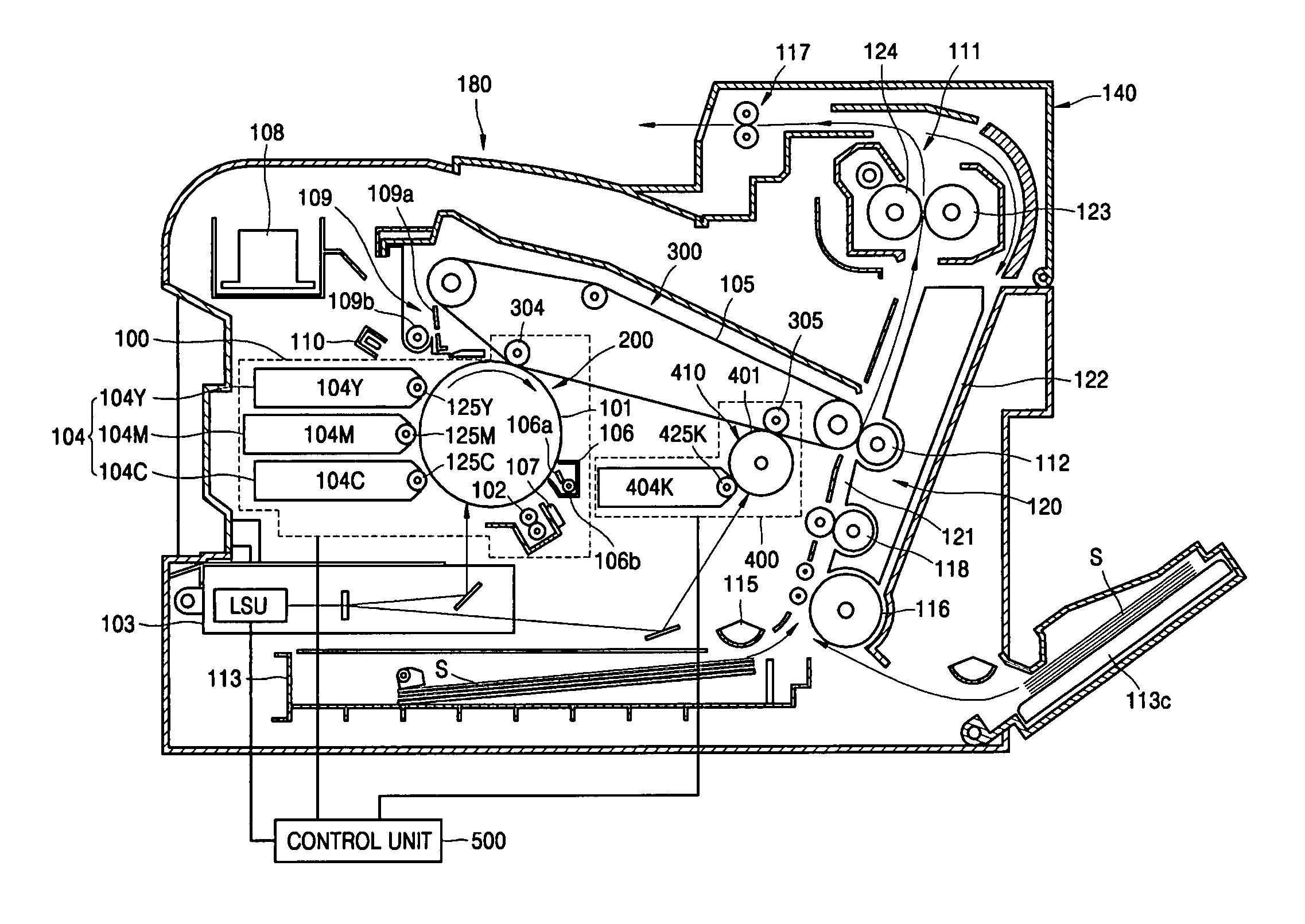
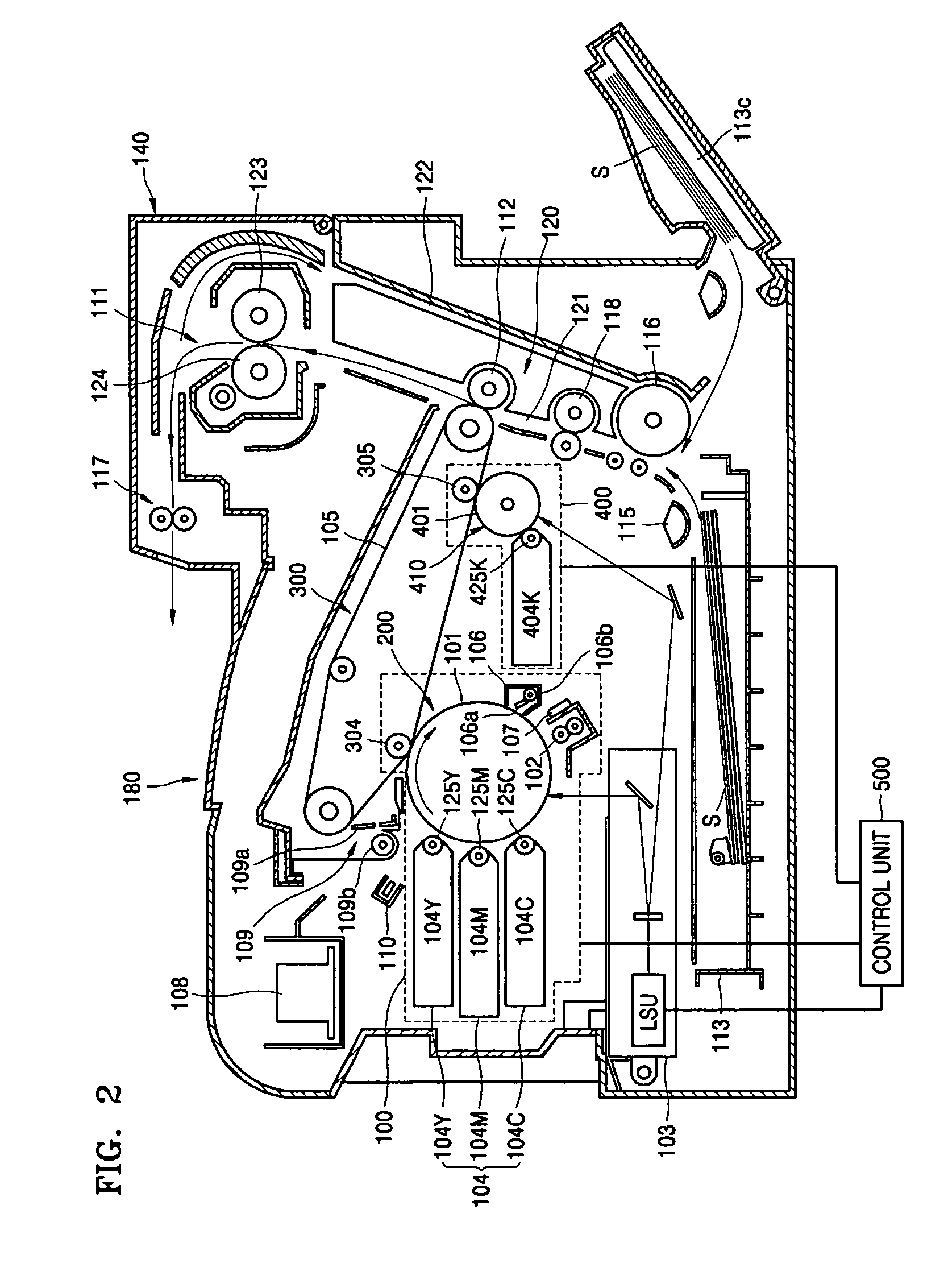
[0041]FIG. 2 is a sectional view of an image forming apparatus according to an embodiment of the present invention, FIG. 3 is a perspective view of a first photoconductive unit of FIG. 2, and FIG. 4 is a perspective view of an intermediate transfer device of FIG. 2. In addition, FIG. 5 is a schematic sectional view of first and second image forming units and the intermediate transfer device of FIG. 2. Since configurations and operations of a second photoconductive unit are similar as in the first photoconductive unit of the FIG. 3, a detailed description for this will be omitted.

[0042] As shown in FIG. 2, a first image forming unit 100, a second ima...


PUM


Abstract

An image forming apparatus, including a first image forming unit, including a first photoconductor and a first developing device that develops an image by supplying toner onto an electrostatic latent image formed on the first photoconductor, a second image forming unit, including a second photoconductor and a second developing device that develops an image by supplying toner onto an electrostatic latent image formed on the second photoconductor, and a control unit to control operations of the second image forming unit, so that, when the first image forming unit is not installed in the image forming apparatus, the image is printed in response to desired image data by an operation of the second image forming unit.

Description

CROSS-REFERENCE TO RELATED APPLICATION [0001] This application claims the benefit of Korean Patent Application No. 2005-105578, filed on Nov. 4, 2005, in the Korean Intellectual Property Office, the disclosure of which is incorporated herein in its entirety by reference. BACKGROUND OF THE INVENTION [0002] 1. Field of the Invention [0003] An aspect of the present invention relates to an image forming apparatus, and, more particularly, to an image forming apparatus that prints a mono-chromatic image regardless of a state of installation of a color developing unit and has an improved printing speed when printing a color image and a printing method thereof. [0004] 2. Description of the Related Art [0005] Generally, a common image forming apparatus has a charging process in which the surface of a photoconductor is charged to have a predetermined electric potential, an exposing process in which an electrostatic latent image is formed by illuminating light onto the surface of the photocond...

Claims


Application Information

Patent Timeline
IPC IPC(8): G03G15/01
CPCG03G2215/00025G03G15/0131G03G15/0184G03G2215/0106G03G15/02
Inventor SEO, IN-SIKYANG, MYUNG-WOO
Owner S PRINTING SOLUTION CO LTD
Why Eureka
Try Eureka