
Planar vibration absorber

Inactive Publication Date: 2007-06-14
NORTHROP GRUMAN CORP
View PDF10 Cites 45 Cited by
  • Summary
  • Abstract
  • Description
  • Claims
  • Application Information

AI Technical Summary

Benefits of technology

[0008] It will be appreciated from the foregoing summary that the present invention represents a significant advance in the field of vibration damping of mechanical structures. In particular, the invention provides a tuned mass damper that attenuate...

Problems solved by technology

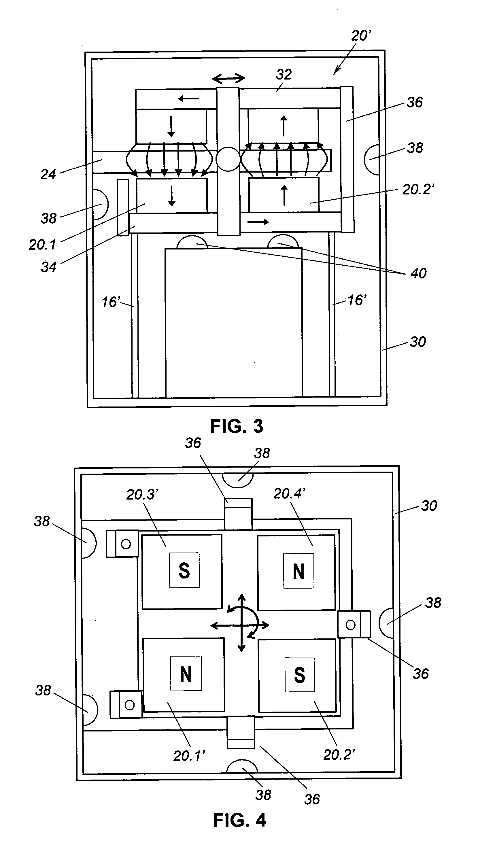
Ideally, the magnet structure comprises four magnetic pole pairs arranged in a symmetrical configuration, since use of fewer di-pole magnets does not provide equal damping force in both orthogonal directions in the selected plane.

Method used


Image

  • Planar vibration absorber
  • Planar vibration absorber
  • Planar vibration absorber

Examples


Embodiment Construction

[0018] As shown in the drawings for purposes of illustration, the present invention pertains to tuned mass damping mechanisms that provide for damping of mechanical vibrations in multiple directions in a single plane. In accordance with the invention, a moving damper mass is coupled to a vibrating mass through one or more flexures designed to permit movement of the damper mass in a selected plane. The one or more flexures are tuned to a known vibration mode of the vibrating mass. The damper further includes a mechanism to damp movement of the moving damper mass with respect to the vibrating mass, as will become clear from the following more detailed description of the several embodiments of the invention.

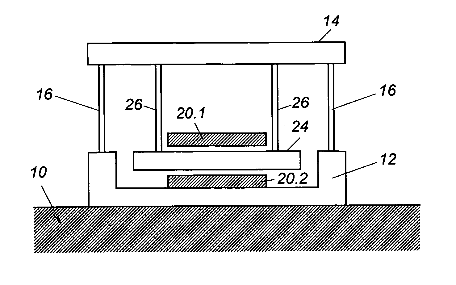
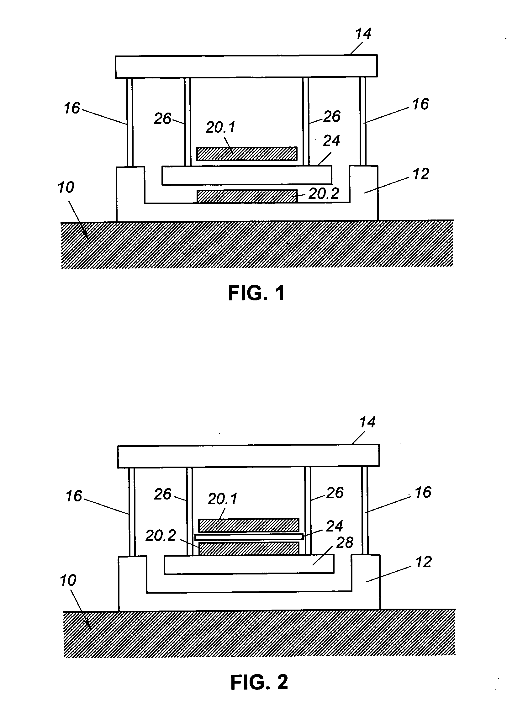
[0019]FIGS. 1 and 2 are diagrammatic views depicting two principal embodiments of the invention. In FIG. 1, a vibrating mass of a structure is indicated by reference numeral 10. The damping mechanism of the invention includes a frame member 12 rigidly attached to the vibrating mass...


PUM


Abstract

A tuned mass damper for attenuating vibrations in a selected plane of a mechanical structure, by magnetically induced eddy current damping. A moving damper mass is coupled to a vibrating mass through one or more flexures that confine relative movement of the damper mass substantially to the selected plane. A magnet structure is rigidly attached to either the vibrating mass or the damper mass, and a conductor plate is attached to the other of these masses. Movement of the damper mass relative to the vibrating mass induces eddy currents in the conductor plate and thereby generates a damping force that attenuates vibration in the selected plane.

Description

BACKGROUND OF THE INVENTION [0001] This invention relates generally to vibration damping mechanisms and, more particularly, to techniques for damping vibrations that may occur within a geometric plane of a mechanical structure. Mechanical structures of all kinds are subject to unwanted vibrations. Of particular interest are structures that are intended to provide an extremely stable platform for precision equipment, such as space-based telescopes. Vibrations may be due to related motors and other equipment. Without damping, vibrations may resonate with structural members and render the equipment inoperative or, at worst, may cause damage to the structure or its supported equipment. [0002] Ideally, damping should be achieved inertially without introducing a damper into a load path associated with the damped structure, which may distort a critical aspect of damped structure. The damping mechanism should preferably provide damping effectiveness in multiple directions, such as a single ...

Claims


Application Information

Patent Timeline
IPC IPC(8): F16F7/10
CPCF16F15/035
Inventor BRONOWICKI, ALLEN J.BRENNAN, SARAH M.SIMONIAN, STEPAN S.
Owner NORTHROP GRUMAN CORP
Learn More