Spatial light modulator apparatus and method

a technology of spatial light and modulator, which is applied in the field of microscopy systems, can solve the problems of inability to clearly view the object of interest, phototoxicity and/or photobleaching, and particularly troubling problems

Inactive Publication Date: 2007-06-14
TANG CHA MIN +1
View PDF3 Cites 55 Cited by
  • Summary
  • Abstract
  • Description
  • Claims
  • Application Information

AI Technical Summary

Problems solved by technology

Problems arise from these known systems of illumination, however, as there are situations where it may be better to vary the intensity of illumination over different regions of the specimen.
For instance, during live cell imaging only a portion of the field of view is of interest and unnecessary exposure of light to living tissue in the remainder of the field can result in photo-toxicity and/or photo-bleaching.
An additional problem occurs when a bright object is located in front or in back of a structure of interest, making it impossible to clearly view the object of interest.
Photo-toxicity is a particularly troubling problem in live cell fluorescence microscopy.
First, fluorescence microscopy requires very intense excitation illumination that is typically many orders of magnitude brighter than that used for conventional brightfield microscopy.
Photo-toxicity due to an intense excitation illumination light is often the ultimate limitation in live cell

Method used


Image

  • Spatial light modulator apparatus and method
  • Spatial light modulator apparatus and method
  • Spatial light modulator apparatus and method

Examples


Embodiment Construction

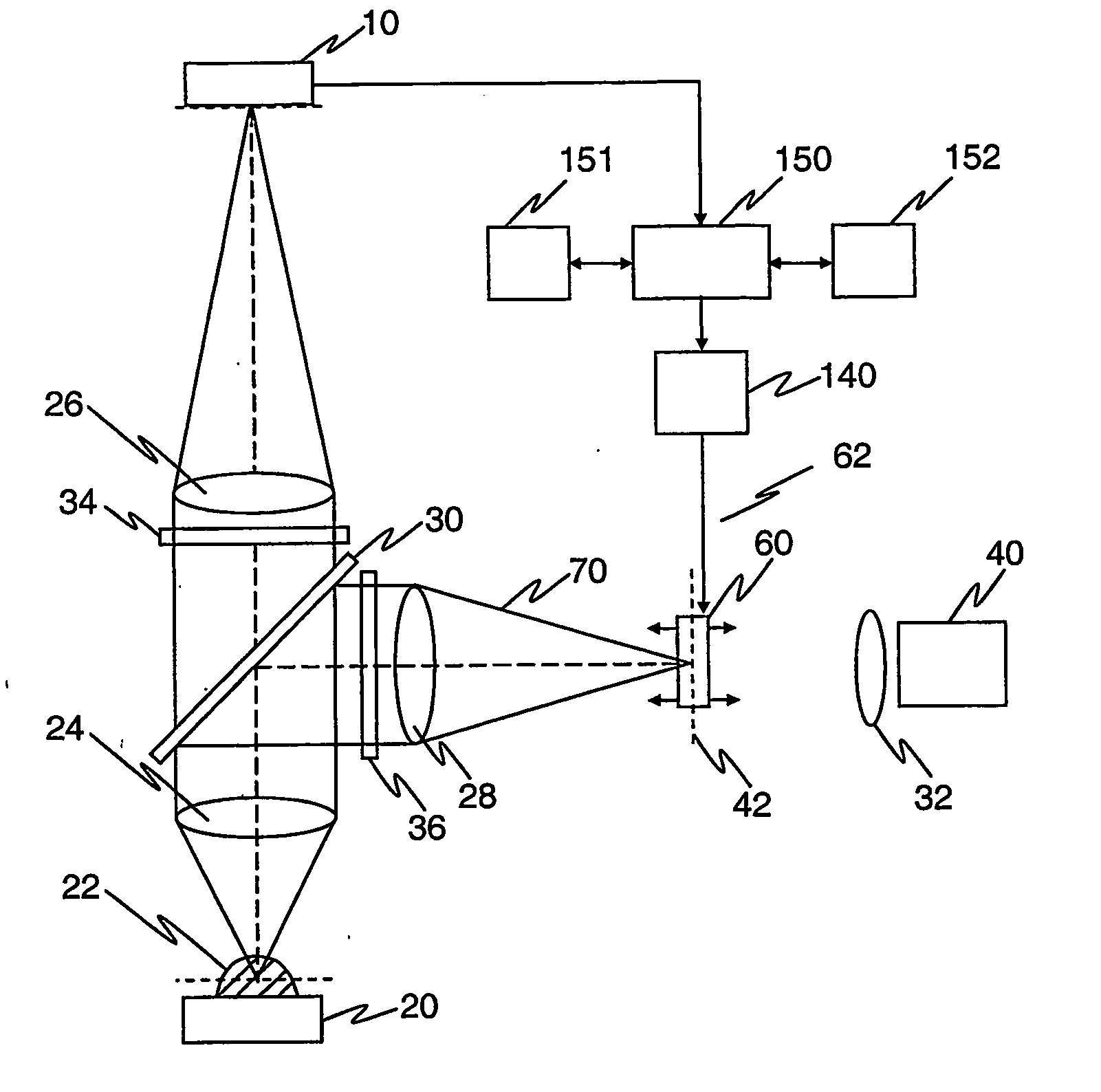
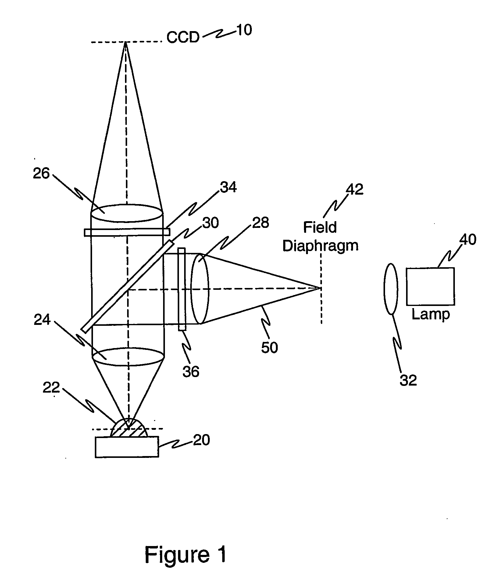
[0049] Enabling examples of the present invention provided herein discuss an epi-illumination fluorescent microscopy apparatus. However, the ordinarily skilled artisan readily comprehends that the invention may be deployed in any type of illumination system utilizing fluorescent microscopy, and / or in non-microscopy applications involving fluorescent emissions. Those of skill in the art readily comprehend that the instant invention may be deployed with any type of stimulating light illumination system used for stimulating a sample to produce excited fluorescence and / or for confocal masking.

[0050] Achieving optimal image quality using a CCD detector requires that the sample being viewed possess an emitted light signal intensity that is within the linear range of the CCD. The present invention achieves this goal by adaptively modulating excitation illumination intensity on a pixel-by-pixel basis using a high resolution spatial light modulator, such as an LCD (liquid crystal display) o...


PUM


Abstract

A device for discriminately illuminating a sample (22) to be viewed with excitation light (70). For example, an image taken with a CCD (10) provides feedback which is used to modulate the output of an excitation light source (40), thereby allowing a sample (22) to be viewed within the optimal range of detection for the particular CCD device (10) being used, despite the potential of wide dynamic ranges of sample luminescence.

Description

CROSS-REFERENCE TO RELATED APPLICATIONS [0001] This application claims the benefit of Provisional Application No. 60 / 514,888 filed in the U.S.P.T.O. on Oct. 28, 2003. The present application incorporates the disclosure of this provisional application by reference.FIELD OF THE INVENTION [0002] This invention relates to microscope systems that utilize spatial light modulators for illuminating a specimen, for example, fluorescent microscopes. BACKGROUND OF THE INVENTION [0003] Microscopes are well-established instruments for observing minute biological structures and processes. This field of art includes fluorescent microscopy, which allows a user to achieve a high degree of target specificity and image contrast for biological specimens. Conventional fluorescent microscopes employ the basic illumination scheme shown in FIG. 1. In FIG. 1, a viewing device 10 (such as a Charged Coupled Device (CCD) or camera or eye) is used to observe a biological sample 22 which rests upon stage 20. The...

Claims


Application Information

Patent Timeline
IPC IPC(8): G01N21/64G02B
CPCG01N21/6458G01N2201/0635
Inventor TANG, CHA-MINBARTFAY-SZABO, ANDREW
Owner TANG CHA MIN
Why Eureka
Try Eureka