Eureka AIR delivers breakthrough ideas for toughest innovation challenges, trusted by R&D personnel around the world.

Ink jet recorder

Inactive Publication Date: 2001-07-10
BROTHER KOGYO KK
View PDF1 Cites 25 Cited by
  • Summary
  • Abstract
  • Description
  • Claims
  • Application Information

AI Technical Summary

Benefits of technology

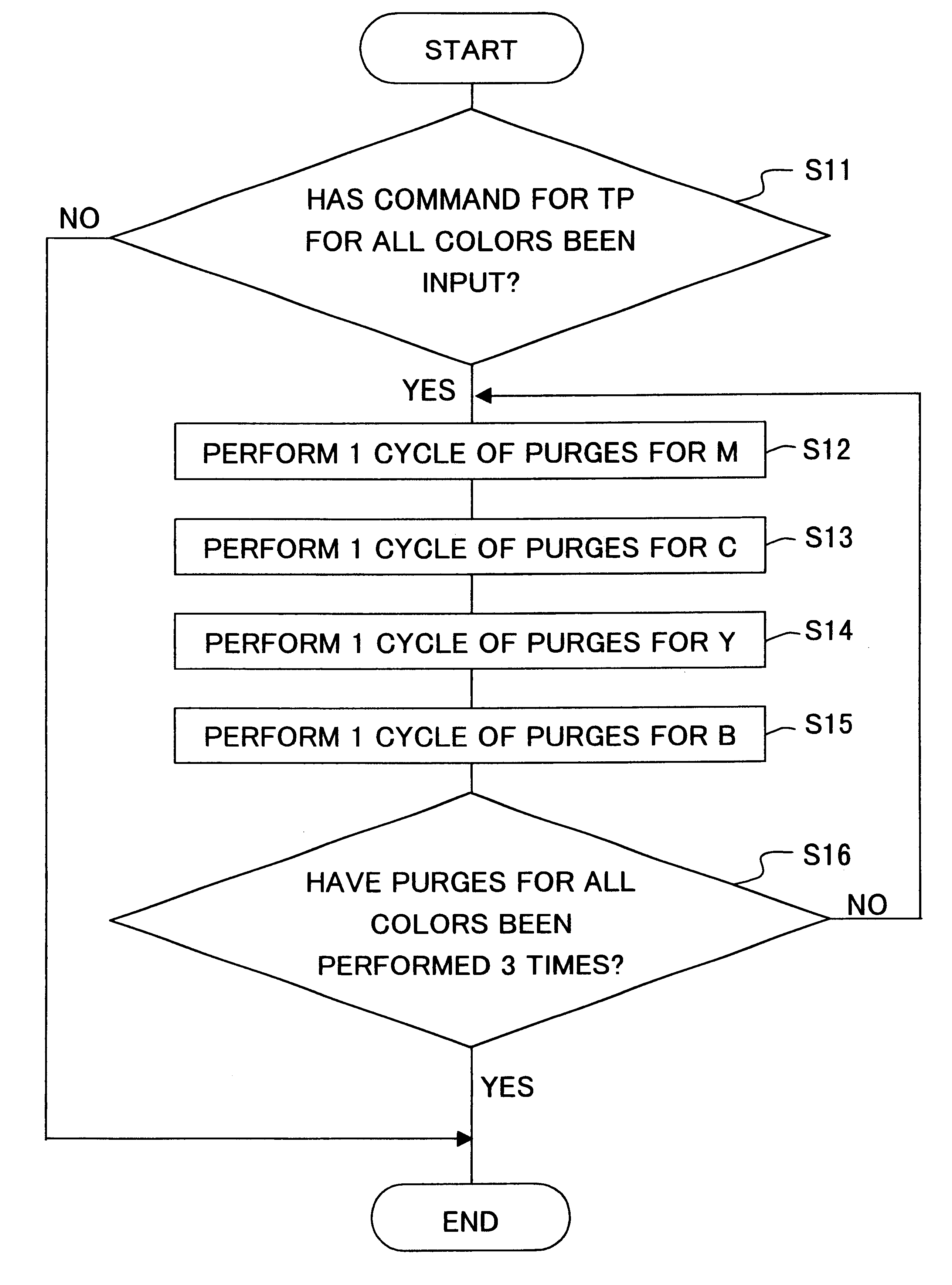
Inks used for the ink jet recorder are different from each other in a tendency of drying depending on component and composition of wetting agent, dye and like included therein. Accordingly, in the present invention, the purging operation for the plurality of ejection nozzles are performed in such manner that the nozzle for ejecting the ink with higher dry resistance is purged before the other nozzles ejecting the inks with lower dry resistance. Namely, as the ink has lower dry resistance, the corresponding nozzle to the ink is purged later. Therefore, each nozzle can be prevent from drying during the purging operation and an excellent recording can be maintained, especially in an initial recording stage subsequent to the purging operation.
The ink jet recorder according to the invention may further comprise a memory storing information on dry resistance characteristics of the different inks. In the ink jet recorder, the ejection surfaces may be arranged so as to be lined up from one end of the recording head according to the dry resistance characteristics of inks ejected from the ejection surfaces. Thereby, movement of the recording head relative to the purging device can be minimum and time for the purging operation can be shortened.
According to a second aspect of the invention, a purging method for an ink jet recorder comprising a recording head having a plurality nozzles for ejecting a plurality of colored inks and a purging device capable of purging one of nozzles at time, characterized in that a nozzle having an ink with higher dry resistance is purged before a nozzle having an ink with lower dry resistance is provided. Thereby, the nozzles of a recording head can be prevented from drying to ensure high recording quality.

Problems solved by technology

However, when the purging operation is performed in order of lighter color inks, there is a problem that some color inks tend to dry during the operation, because only one nozzle can be capped by the cap p6 at a time.

Method used


Image

  • Ink jet recorder
  • Ink jet recorder
  • Ink jet recorder

Examples


Embodiment Construction

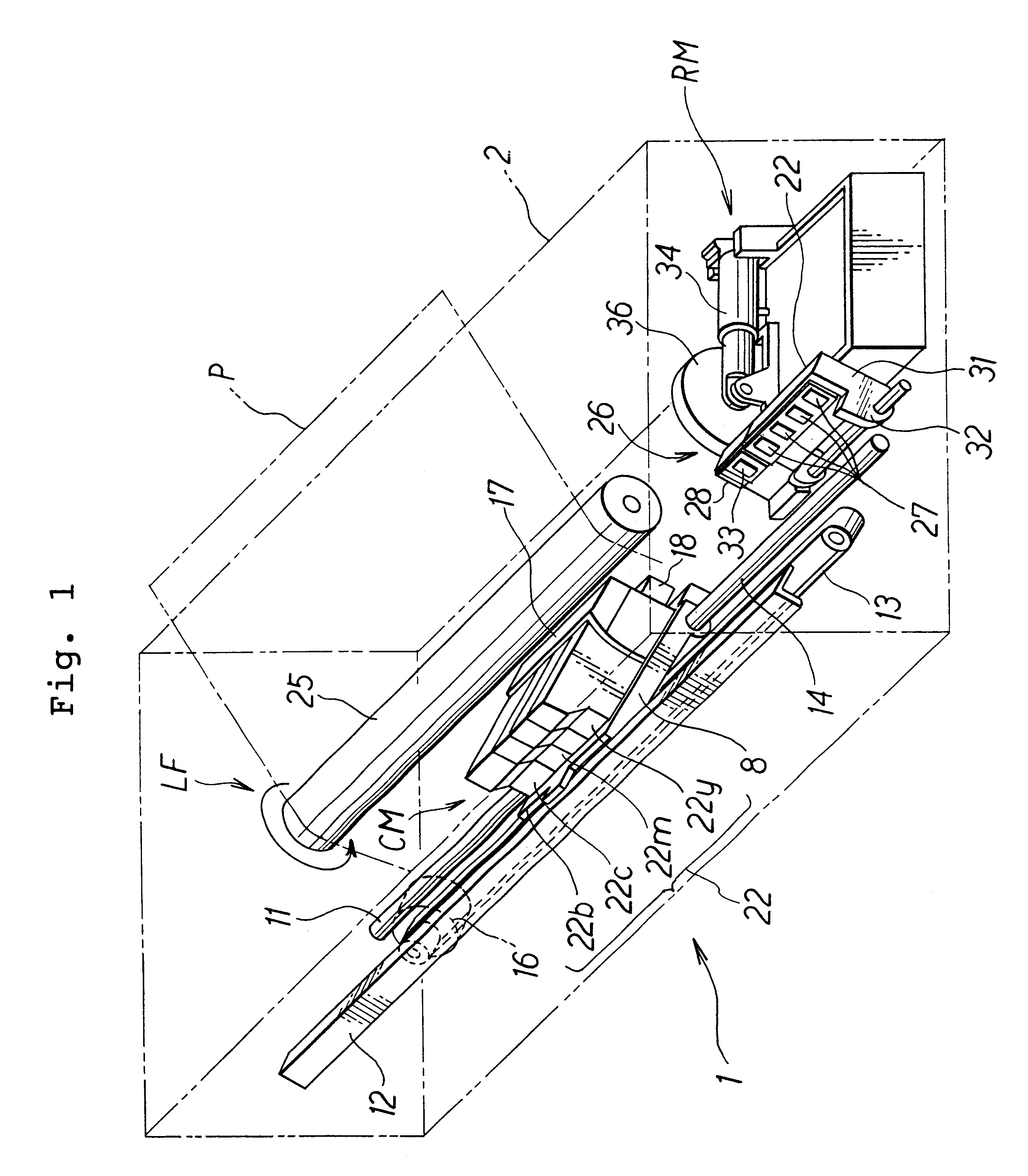
FIG. 1 shows the internal structure of an ink jet printer 1 according to an embodiment of the invention. The printer 1 includes a frame 2. A guide rod 11 and a guide member 12 extend horizontally in parallel, and are fixed to the frame 2. A carriage 8 is supported slidably on the rod 11 and member 12, and is fixed to a timing belt 13, which can be driven by a carriage drive motor (CR motor) 16 in order for the carriage 8 to reciprocate along the rod 11 and member 12. Mounted on the carriage 8 is an ink jet type recording head unit 17, which includes a recording head 18 for printing a recording sheet or medium P by ejecting droplets of ink of four colors (cyan C, magenta M, yellow Y and black B) onto the sheet.

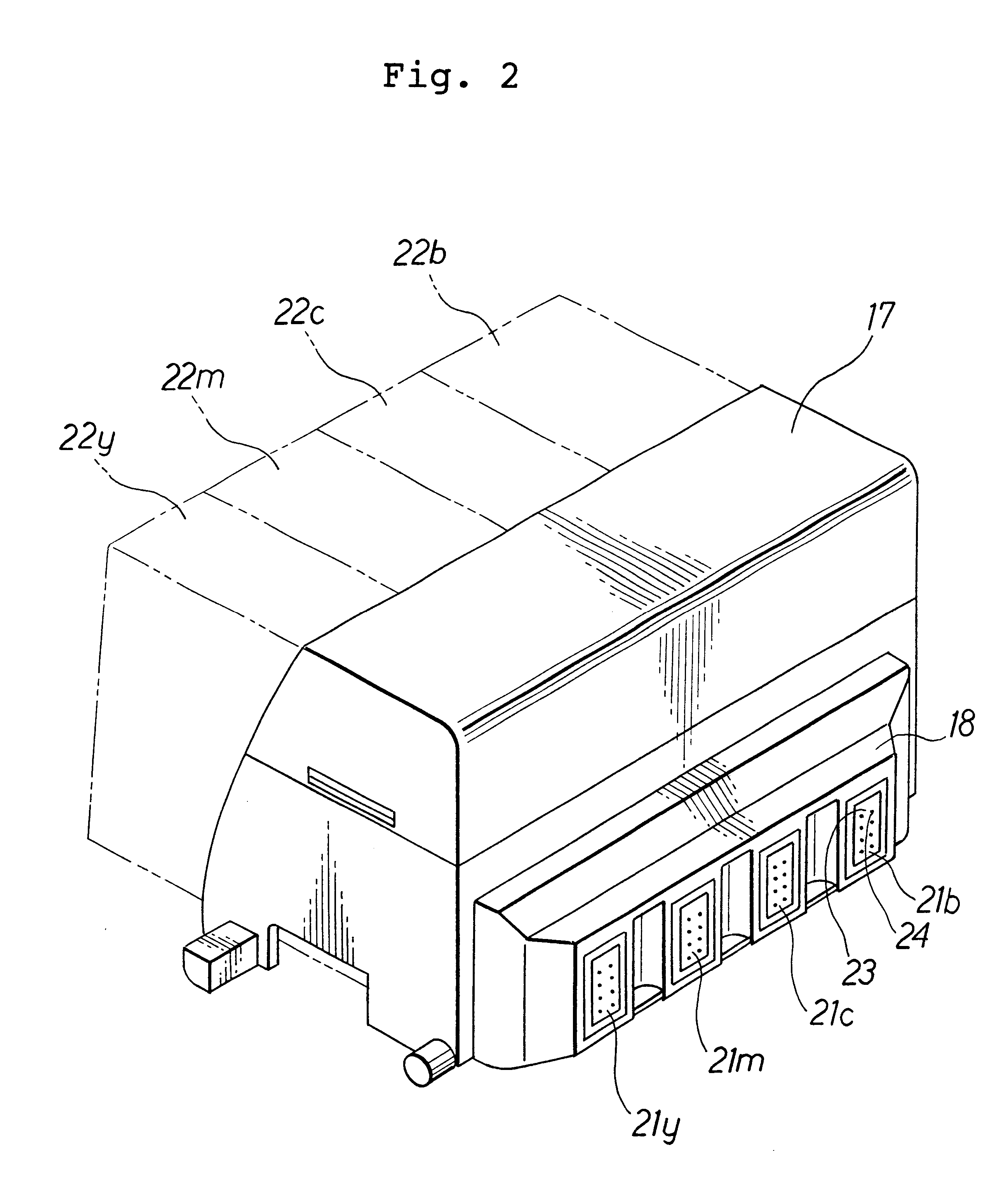
As shown in FIG. 2, the recording head 18 has injection nozzles 21 (21y, 21m, 21c, 21b). Mounted removably on the back side of the head unit 17 are ink cartridges 22 (22y, 22m, 22c, 22b) for supplying the nozzles 21y, 21m, 21c and 21b, respectively, with inks. Each nozzle 21 ha...


PUM


Abstract

An ink jet recorder includes a recording head having a plurality of ejection surfaces each containing a nozzle for ejecting a different ink, a purging device for purging the nozzle of one ejection surface at a time and a controller for the purging device. The controller controls the purging device such that a nozzle having an ink with higher dry resistance is purged before a nozzle having an ink with lower dry resistance. The ink jet recorder can prevent the nozzles from drying during the purging operation.

Description

1. Field of the InventionThe present invention relates to an ink jet recorder, such as an ink jet printer having a purging apparatus for sucking ink from a ink jet head and a purging method therefor.2. Description of Related ArtInk jet printers are known generally as ink jet recorders for recording on recording media, such as sheets of paper, by ejecting ink onto them. FIG. 9 of the accompanying drawings shows part of a conventional ink jet printer, which includes a recording head unit P3 having a recording head P2. The head P2 has four ejection nozzles P4, each of which has ejection holes (not shown) opening in its front surface P5. The ejection nozzles eject different colored inks including black, yellow, cyan and magenta, respectively. Four ink cartridges P1 containing the respective colored inks are mounted replaceably on the head unit P3, and each connected to the corresponding nozzle P4. After each cartridge P1 is replaced with a new one, ink is supplied from the new cartridge...

Claims


Application Information

Patent Timeline
IPC IPC(8): B41J2/165B41J2/21B41J2/18B41J2/185
CPCB41J2/2107B41J2/16526
Inventor NAKAMURA, HIROTAKE
Owner BROTHER KOGYO KK
Why Eureka
Eureka Blog
Learn More