Fan speed control device and method

a control device and fan technology, applied in the direction of motor/generator/converter stopper, dynamo-electric converter control, instruments, etc., can solve the problems of increased power consumption, easy generation of heat, and inability to easily dissipate heat, so as to reduce the noise caused by the switch switching, reduce the noise, and reduce the effect of nois

Active Publication Date: 2007-06-14
DELTA ELECTRONICS INC
View PDF1 Cites 0 Cited by
  • Summary
  • Abstract
  • Description
  • Claims
  • Application Information

AI Technical Summary

Benefits of technology

[0009] In view of the foregoing, the invention is to provide a fan speed control device and a fan speed control method, which can decrease the power consumption, reduce the noise of switching, avoid electromagnetic interference, and dissipate heat more efficiently.
[0013] As mentioned above, the fan speed control device and method of the invention combine a voltage control and a pulse width modulation (PWM) control. In other words, a voltage regulator and a switch are provided in series between a motor of the fan and the power source, and a controller is used to control the voltage regulator and switch. When the rotation speed of the fan is faster, the switch is controlled with a pulse width modulation signal for controlling the rotation speed of the fan. In this case, because the wind sound generated by the rotated fan is louder, the switching of the switch is not obvious and won't enlarge the noise. When the rotation speed of the fan is slower, the pulse width modulation signal is fixed, and the voltage regulator is controlled with a voltage signal for further lowering the rotation speed of the fan. In this case, because the voltage and current of the switch are small and are constant, the noise caused by the switching of the switch can be decreased, and the electromagnetic interference can be greatly reduced. Then, the voltage regulator is enabled. Since small a voltage is capable of changing the rotation speed of the fan, the power consumption can be reduced and the heat-dissipating problem of the voltage regulator can be solved.

Problems solved by technology

However, although the above-mentioned control method can easily change the rotation speed of the fan 1 by changing the voltage VT of the linear voltage regulator 12, it may cause the increased power consumption.
In addition, since the linear voltage regulator 12 is constantly working and changing voltage, it generates heat easily and the heat is not easily dissipated.
However, the noise caused by the switching of the power switch element 22 is obvious when the fan 2 is at a low rotation speed.
As shown in FIG. 3, the switching of the fan 2 may lead to the rapid changes of the voltage (ΔV) and the current variations per unit time (di / dt), which results in higher electromagnetic interference.

Method used


Image

  • Fan speed control device and method
  • Fan speed control device and method
  • Fan speed control device and method

Examples


Embodiment Construction

[0021] The present invention will be apparent from the following detailed description, which proceeds with reference to the accompanying drawings, wherein the same references relate to the same elements.

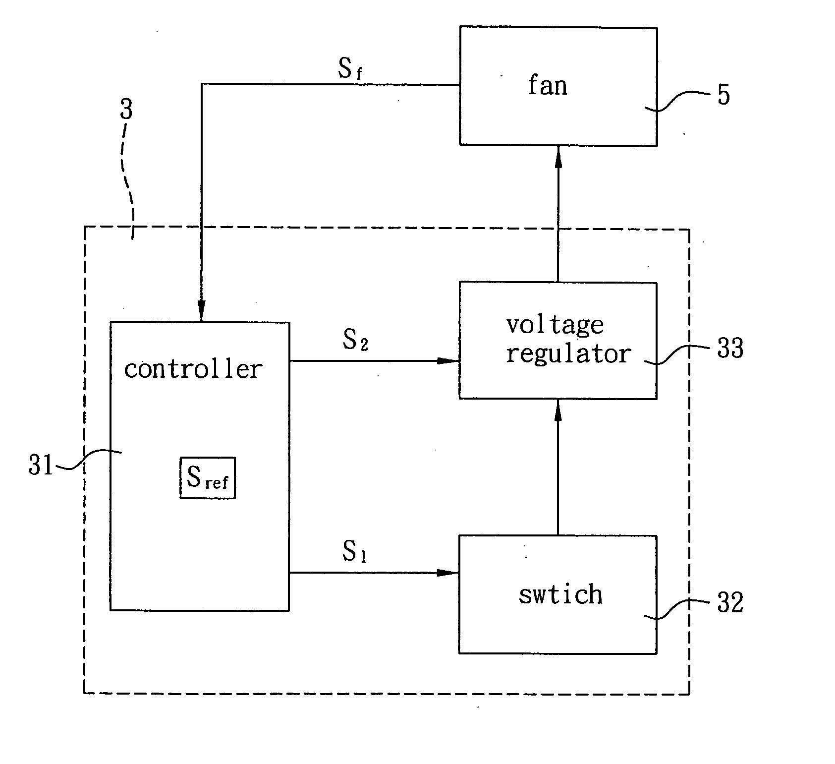
[0022] With reference to FIG. 4, in a preferred embodiment of the invention, a fan 5 has a fan speed control device 3, which comprises a controller 31, a switch 32 and a voltage regulator 33.

[0023] The controller 31 detects a rotation speed signal Sf of the fan 5. When the rotation speed signal Sf is relatively higher than a predetermined rotation speed signal Sref, the controller 31 generates a first driving signal S1. In addition, when the rotation speed signal Sf is relatively lower than the predetermined rotation speed signal Sref, the controller 31 generates the first driving signal S1 and a second driving signal S2. In this embodiment, the controller 31 can be an integrated circuit (IC) or a programmable control single chip.

[0024] In this embodiment, the first driving signal...


PUM


Abstract

A fan speed control device includes a controller, a switch and a voltage regulator. The controller detects a rotation speed signal of the fan to generate a first driving signal when the rotation speed signal is relatively higher than a predetermined rotation speed signal and generates the first driving signal and a second driving signal when the rotation speed signal is relatively lower than the predetermined rotation speed signal. The switch is electrically connected with the controller and receives the first driving signal. The voltage regulator, which is electrically connected with the controller, the switch and the fan, receives the second driving signal, and controls the rotation speed of the fan in accordance with the first driving signal and the second driving signal.

Description

CROSS REFERENCE TO RELATED APPLICATIONS [0001] This Non-provisional application claims priority under 35 U.S.C. §119(a) on Patent Application No(s). 094143294 filed in Taiwan, Republic of China on Dec. 8, 2005, the entire contents of which are hereby incorporated by reference. BACKGROUND OF THE INVENTION [0002] 1. Field of Invention [0003] The invention relates to a rotation speed control device and method, and, in particular, to a rotation speed control device and method for controlling the rotation speed of a fan. [0004] 2. Related Art [0005] Most electronic systems are equipped with a fan for heat dissipation so as to prevent some elements in the electronic systems from being over-heated and producing glitches. [0006] As shown in FIG. 1, a conventional fan 1 includes a motor 11. If the motor 11 is a DC brushless motor, the rotation speed and voltage VM of the motor 11 are directly proportional. To control the rotation speed of the fan 1, the motor 11, which is electrically connec...

Claims


Application Information

Patent Timeline
Patent Type & Authority Applications(United States)
IPC IPC(8): G05F1/10H02P25/098H02P29/00H02P29/60
CPCH02P7/2885H02P7/2913
Inventor CHIU, CHUN-LUNGTSAI, MING-SHIHUANG, WEN-SHI
Owner DELTA ELECTRONICS INC
Why Eureka
Try Eureka