Degaussing for write head

a write head and degaussing technology, applied in the field of hard disk drives, can solve problems such as erasing some data

Inactive Publication Date: 2007-07-05
TEXAS INSTR INC
View PDF16 Cites 9 Cited by
  • Summary
  • Abstract
  • Description
  • Claims
  • Application Information

AI Technical Summary

Benefits of technology

[0006] The present invention achieves technical advantages as a write head degaussing circuit and methodology that ends the degaussing process when the current Iw is selectable percentage short of th...

Problems solved by technology

Usually, the write head current Iw is shut off during the read process, but some head (pol...

Method used


Image

  • Degaussing for write head
  • Degaussing for write head
  • Degaussing for write head

Examples


Embodiment Construction

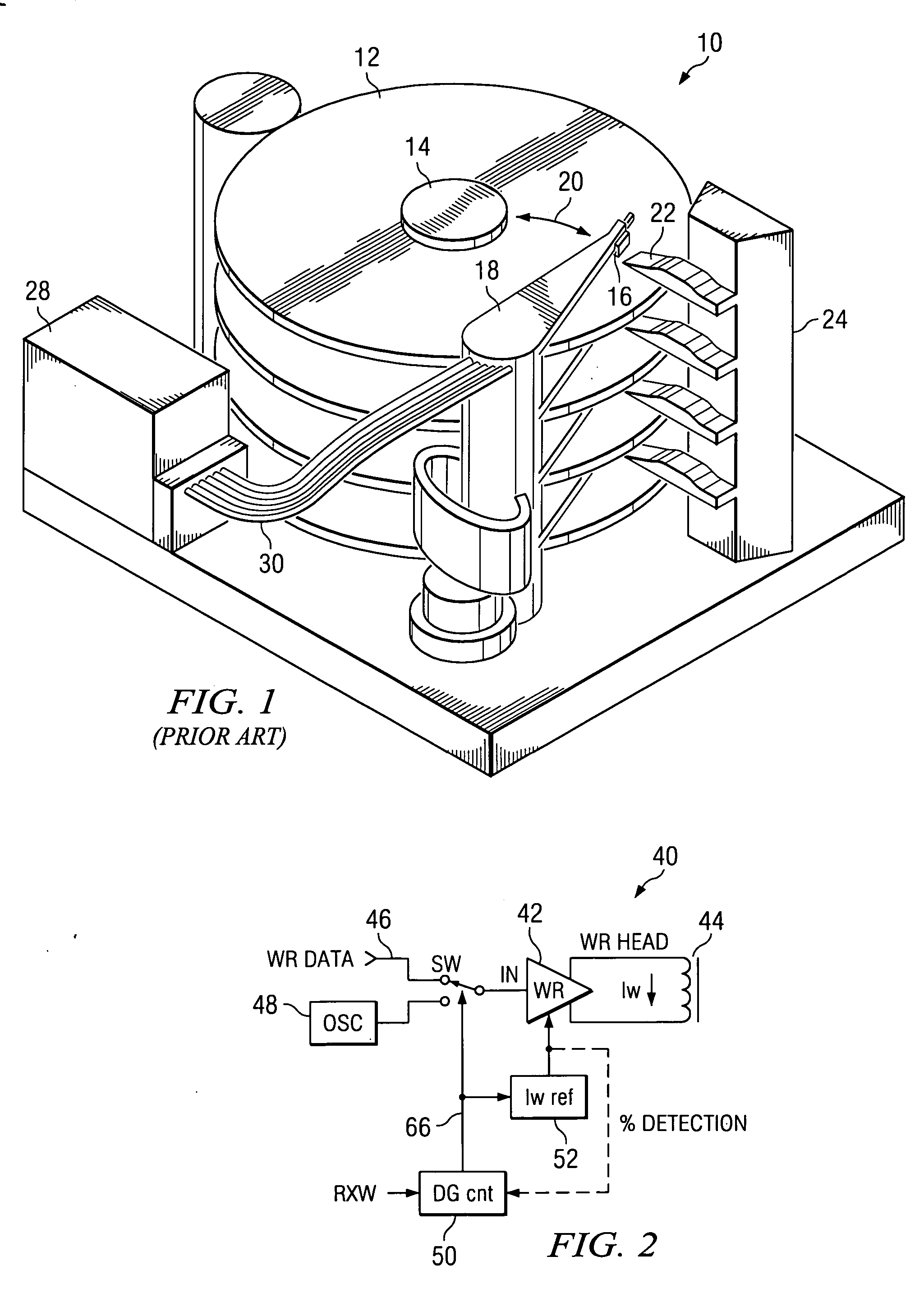
[0015]FIG. 1 depicts a conventional hard disk drive 10 having a plurality of disks and associated actuators positionable between an operational position over the disks and a retracted parked position. Each disk 12 is seen to be mounted to a spindle 14 and has associated therewith a head 16 carried by a suspension arm 18. Each head 16 is seen to be positioned via the respective arm 18 across the disk surface as depicted at 20, and is also retractable over a ramp 22 to a parked position distal of the head 22 and over lower portion 24. An actuator control circuit 26 disposed within a housing 28 is coupled to and controls each of the arms 18 via a cable 30.

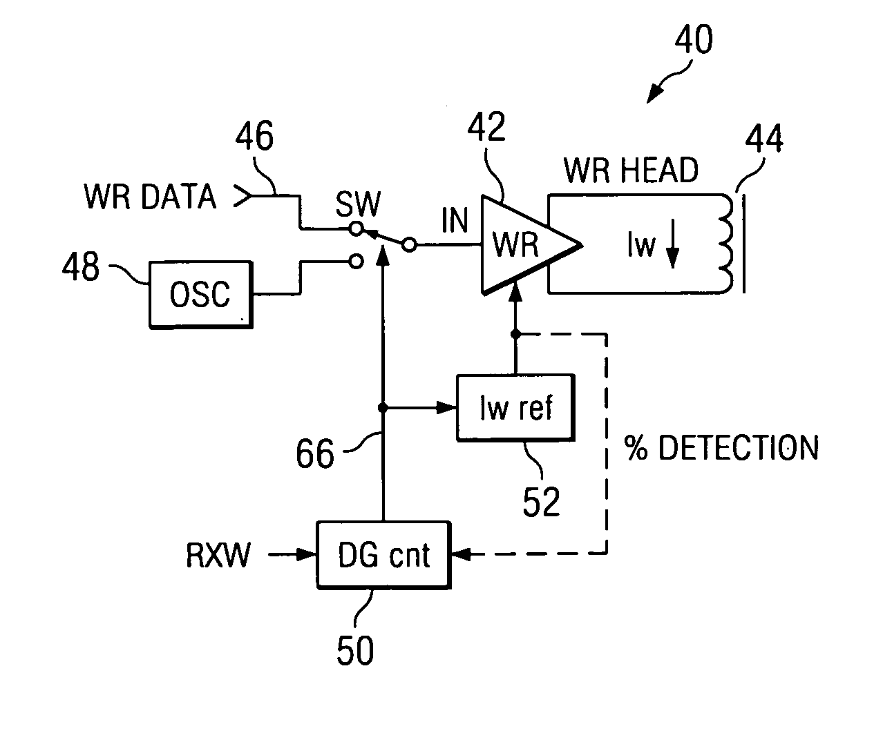
[0016] Referring now to FIG. 2, there is shown a block diagram of a write circuit at 40. Write circuit 40 is seen to include a write head driver 42 driving a voice coil 44, and having an input selectably coupled to either the write data input line 46 or an oscillator 48 via a switch Sw. When the driver input is driven by the oscillat...


PUM


Abstract

A write head degaussing circuit and methodology configured to end the degaussing signal a selectable percentage short of the tapered degaussing waveform, starting the degaussing of the write head current Iw at a percentage less than Iw, removing any overshoot of the degaussing signal, and any combination of the above.

Description

FIELD OF THE INVENTION [0001] The present invention is generally related to hard disk drives, and more particularly to degaussing a write head. BACKGROUND OF THE INVENTION [0002] A hard disk drive typically includes one or more spinning disks stacked above each other on a spindle, a disk drive controller, a rotary actuator and an actuator retract circuit. These elements typically reside in a chassis or housing and are supplied with external cable connectors. [0003] The rotary actuator consists of an arm equipped with a head for reading and writing data in generally radial and concentric tracks in the recording layers of the individual disk. The actuator is usually driven by an attached voice coil motor (VCM). Cables are connected with the actuator to facilitate transmitting signals to and from the head and to power the VCM. The disk drive controller is typically an electronic circuit that controls all functions of the hard disk drive. [0004] During the writing process, the write hea...

Claims


Application Information

Patent Timeline
IPC IPC(8): G11B5/03
CPCG11B2005/0018G11B5/465
Inventor HASHIZUME, MOTOMUHIROSAWA, TAKASHI
Owner TEXAS INSTR INC
Why Eureka
Try Eureka