Display holder

a technology for display holders and display holders, applied in the field of display holders, can solve the problems of limited protection of the contents of the display holders, lack of elements that can thwart unauthorized access, alteration or removal of the printed material held in the display holders, and lack of quick or easy access to printed materials. , to achieve the effect of quick and simple insertion and removal of objects

Inactive Publication Date: 2007-07-12
WOLFE ARNOLD
View PDF23 Cites 4 Cited by
  • Summary
  • Abstract
  • Description
  • Claims
  • Application Information

AI Technical Summary

Benefits of technology

[0008] It is another object of the invention to provide a display holder that enables quick and simple insertion and removal of objects.

Problems solved by technology

Certain sign holders have an open end at the top, or open sides to enable the insertion of printed material (e.g., see U.S. Pat. No. 6,151,822), but such holders offer only limited protection of the contents of the holder, and do not provide a quick or easy way to access the printed material that is inserted into the holder.
The challenge of protecting an advertisement, while still providing quick and easy access to the printed material that has been inserted, is the objective of some advertisement holders (e.g., see U.S. patent application Ser. No. 10 / 794,670), but articles of manufacture such as these fail to offer elements that can thwart unauthorized access, alteration, or removal of the printed material held in the holder.
These sign holders have sacrificed security of the image for accessibility.
This holder addressed security concerns, but the drawback was that by requiring a specialized tool sign accessibility had been complicated rather than made easier.
Furthermore, besides not offering greater accessibility with surer security in a single sign holder, prior sign holders also have failed to provide the versatility of enabling printed material to be displayed on either side of the holder along with the other aforementioned features.
Moreover, current holders are lacking the capability of accomplishing the objectives above, whilst still enabling the display of printed material on both sides of the holder simultaneously.

Method used


Image

  • Display holder
  • Display holder
  • Display holder

Examples


Embodiment Construction

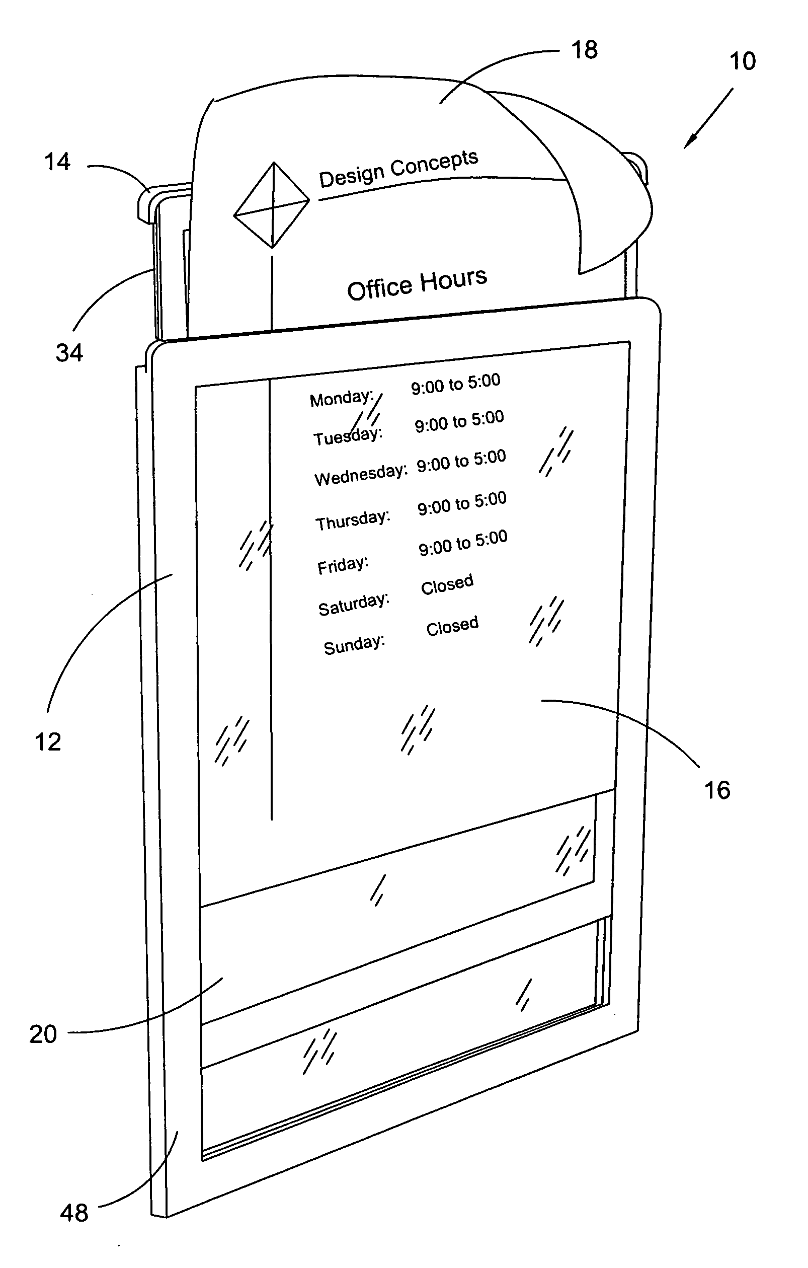
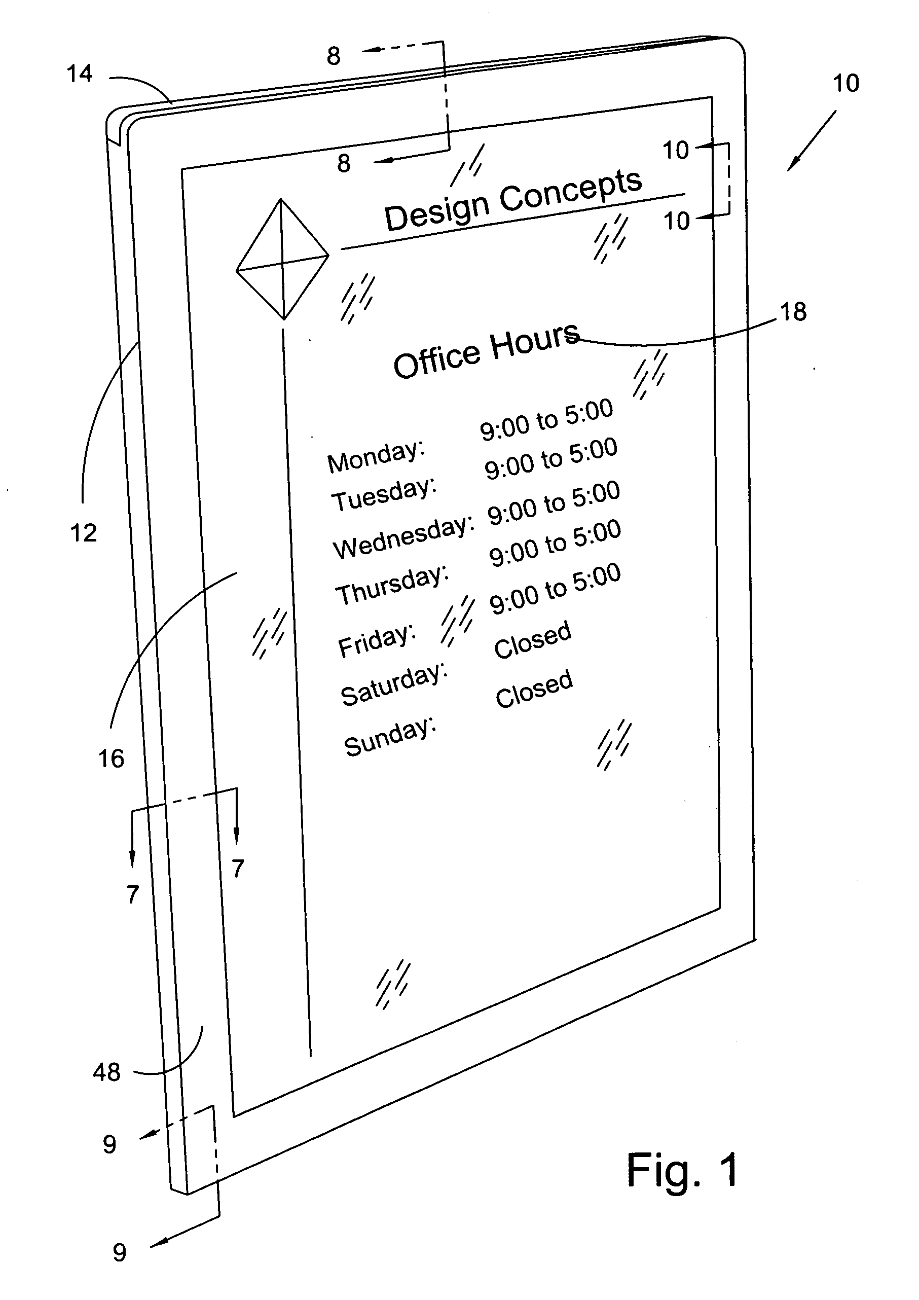
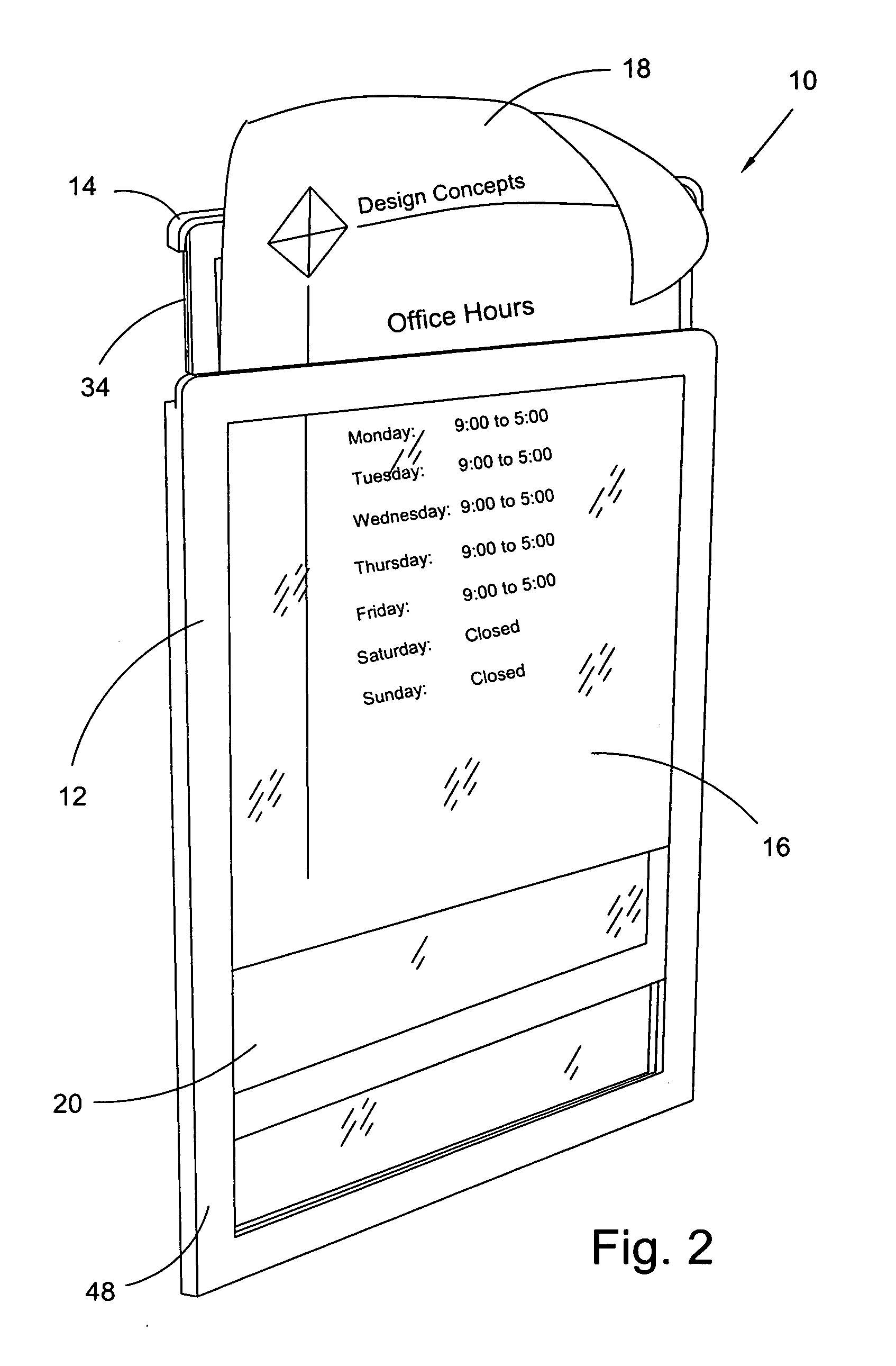
[0024] At the outset, it should be appreciated that like drawing numbers on different drawing views identify identical structural elements of the invention. While the present invention is described with respect to what is presently considered to be the preferred embodiments, it is understood that the invention is not limited to the disclosed embodiments. In the description below, the terms “upper”, “lower”, “front”, “back”, “left”, “right”, and their derivatives, should be interpreted from the perspective of one viewing the display holder shown in FIG. 1.

[0025] Furthermore, it is understood that this invention is not limited to the particular methodology, materials and modifications described and as such may, of course, vary. It is also understood that the terminology used herein is for the purpose of describing particular embodiments only, and is not intended to limit the scope of the present invention.

[0026] Unless defined otherwise, all technical and scientific terms used herei...


PUM


Abstract

A display holder comprising a first and a second panel slidably attached with a space is defined there between. At least a portion of said first or second panels is transparent. In some aspects, the slidable attachment comprises respective tongue and groove elements disposed on longitudinal edges. In other aspects a guide, a stopping means, and a raised portion are disposed on the first or second panels, and a smooth recess is disposed adjacent to the raised portion. Alternatively, an opaque border is disposed around the perimeter of the first and second panels. Furthermore, a locking mechanism is disposed on the first or second panel. In some aspects, the holder can have at least one hanging component which can be an adhesive pad, a suction device, or similar device.

Description

FIELD OF THE INVENTION [0001] This invention relates generally to display holders, specifically to a display holder comprising two clear plastic panels slidably attached, which facilitates the quick and easy changing of the contents of the holder. Alternatively, the holder can provide the capability of displaying signs or notices on both sides of the holder simultaneously. BACKGROUND OF THE INVENTION [0002] Sign holders that provide a casing to hold and display messages are known. Certain sign holders have an open end at the top, or open sides to enable the insertion of printed material (e.g., see U.S. Pat. No. 6,151,822), but such holders offer only limited protection of the contents of the holder, and do not provide a quick or easy way to access the printed material that is inserted into the holder. The challenge of protecting an advertisement, while still providing quick and easy access to the printed material that has been inserted, is the objective of some advertisement holders...

Claims


Application Information

Patent Timeline
Patent Type & Authority Applications(United States)
IPC IPC(8): A47G1/06
CPCG09F7/10
Inventor WOLFE, ARNOLD
Owner WOLFE ARNOLD
Why Eureka
Try Eureka