Fracking multiple casing exit laterals

Active Publication Date: 2007-07-12
BAKER HUGHES INC
View PDF8 Cites 44 Cited by
  • Summary
  • Abstract
  • Description
  • Claims
  • Application Information

AI Technical Summary

Benefits of technology

[0005] A method of fracking multiple laterals sequentially is described. It allows the drilling rig to be moved off site as the laterals are fracked. Thereafter, they can all be produced simult

Problems solved by technology

The problem with this method was the high cost of keeping the drilling rig around while the main lateral was fracked and plugged.
Spacing the frack jobs in time also incurred incremental costs as compared to a frack job on two laterals, if the two laterals could somehow be fracked one after the other.
There were issues with this proced

Method used


Image

  • Fracking multiple casing exit laterals
  • Fracking multiple casing exit laterals
  • Fracking multiple casing exit laterals

Examples


Embodiment Construction

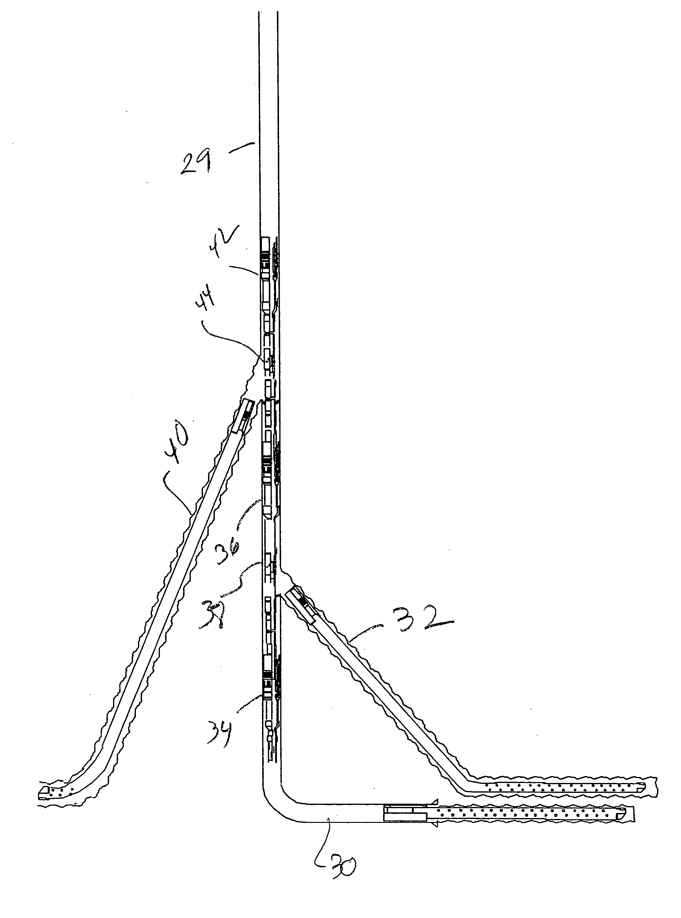
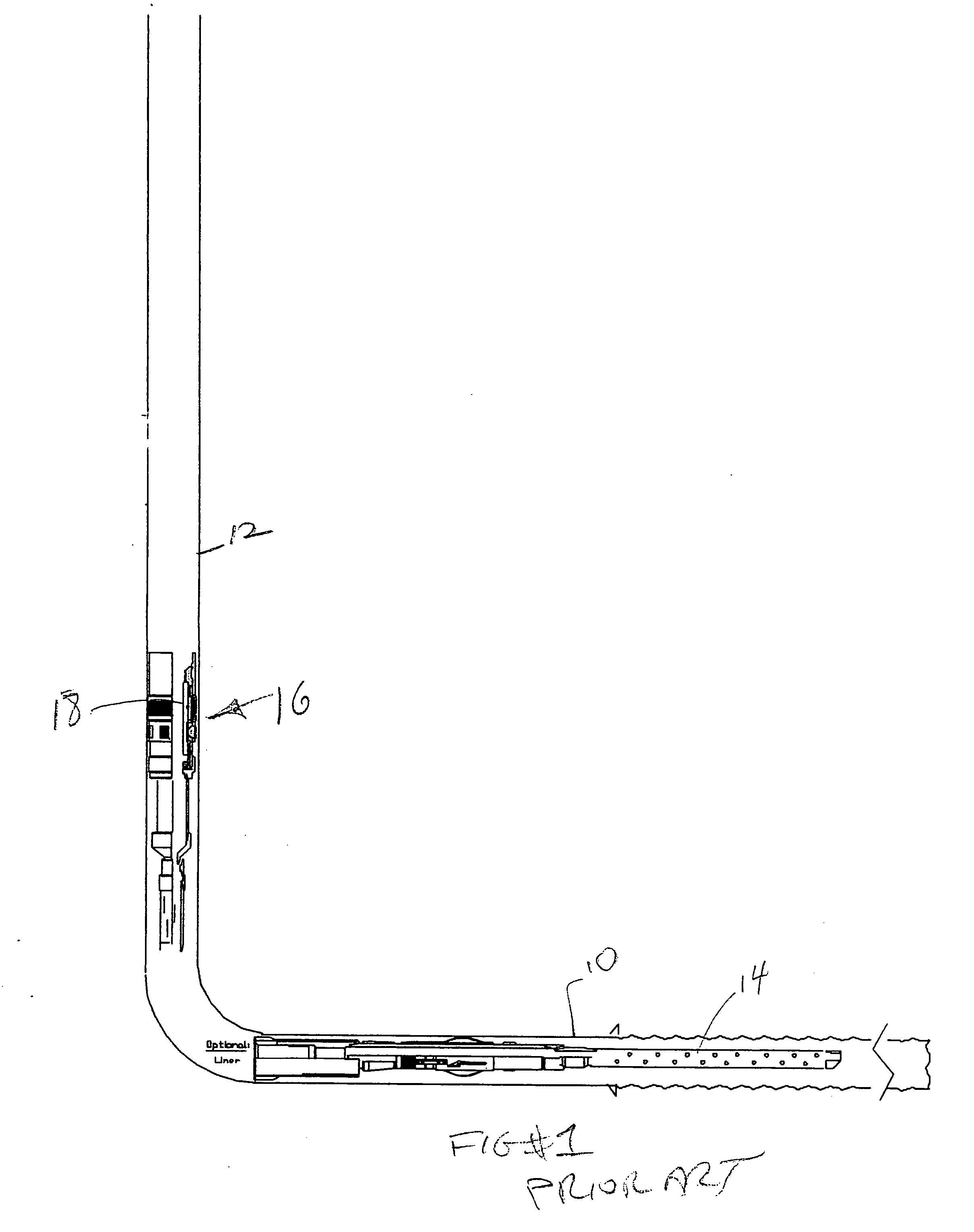
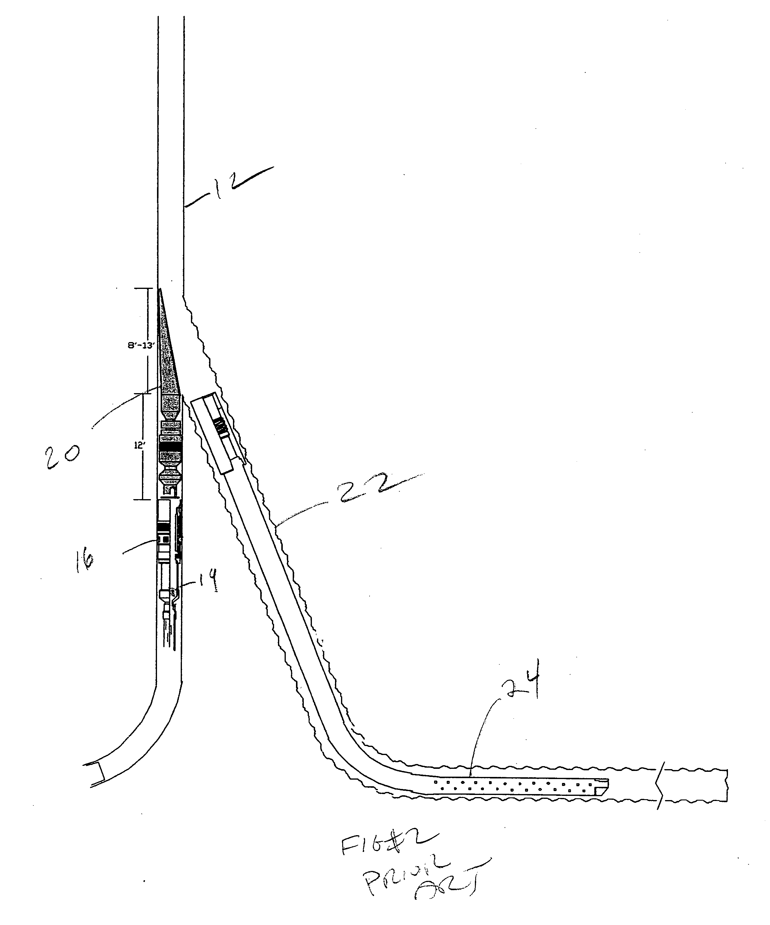
[0013]FIG. 5 is an improvement over the method of FIGS. 1-4 previously described. The method is identical for the drilling of the laterals 30 and 32 and in the use of the packers 34 and 36 and the ported sub 38 between them. Packer 34 has a plug 35 that is later blown out at the start of fracking. The difference starts when after drilling the lateral 32 and setting the packer 36 the packer 36 gets a plug and another whipstock (not shown) is tripped into it to allow the final lateral 40 to be drilled. If required, the lateral 40 is lined and the whipstock is removed and a cleanout process using circulation takes place adjacent packer 36. Thereafter an assembly comprising another packer and a ported sub 44 are tagged into packer 36. With packer 42 set, the fracking can begin, after plug 35 is blown out, and there is no need for the drilling rig or a workover rig to do the fracking. Now with ported subs 38 and 44 both closed to laterals 32 and 40 respectively, a plug dropper is connect...


PUM


Abstract

A method of fracking multiple laterals sequentially is described. It allows the drilling rig to be moved off site as the laterals are fracked. Thereafter, they can all be produced simultaneously. The laterals begin from a main lateral that is already oriented in the producing zone and preferably exit in a coplanar manner so as to extend immediately into the producing formation.

Description

FIELD OF THE INVENTION [0001] The field of the invention is fracking multiple casing exits in a single procedure without having the need for a drilling rig present. BACKGROUND OF THE INVENTION [0002] In the past, the process of drilling laterals was interrupted by fracking the lateral just drilled. In this technique, the drilling rig would drill the main lateral through a shoe in the main bore and then drilling was shut down to perform the fracking on the lateral just drilled into the producing formation. Thereafter, that main lateral was plugged. A whipstock was set higher and a second lateral was drilled from the main bore to exit vertically and eventually enter the producing zone. After the second lateral was drilled it would be temporarily plugged and the drilling rig moved off location. A workover rig was brought on location and the plug was pulled out of the second lateral so that a sand frack in the second lateral could take place. The second lateral would be flowed or produc...

Claims


Application Information

Patent Timeline
IPC IPC(8): E21B43/14E21B43/26
CPCE21B41/0035E21B43/305E21B43/26E21B43/30
Inventor GREEN, RICKEY J.
Owner BAKER HUGHES INC
Why Eureka
Try Eureka