
Techniques for reducing wall thinning during a hydroforming operation

a technology of hydroforming operation and wall thinning, which is applied in the field of hydroforming tubular objects, can solve the problems of substantially even final hydroforming product wall thickness, all thinning, etc., and achieve the effect of reducing the phenomenon of wall thinning

Inactive Publication Date: 2007-07-26
GHARIB MOHAMED
View PDF7 Cites 6 Cited by
  • Summary
  • Abstract
  • Description
  • Claims
  • Application Information

AI Technical Summary

Benefits of technology

The patent text describes a method for reducing the problem of "wall thinning" during the hydroforming process of a work product. By altering the pressure applied to the ends of the tube before hydroforming pressure is applied, the previous problem of "localized wall thinning" is reduced. The method also includes introducing an intermediate cold forming pre-wrinkling hydroforming operation and a preliminary hydroforming technique to produce a work product with a more even wall thickness after the final hydroforming operation. The technical effects of the patent text are improved efficiency and quality of the hydroforming process.

Problems solved by technology

All thinning occurs because of uneven material flow in the various sections of the work product undergoing the hydroforming operation.
This results in a final hydroformed product having substantially even wall thickness after the final hydroforming operation.

Method used


Image

  • Techniques for reducing wall thinning during a hydroforming operation
  • Techniques for reducing wall thinning during a hydroforming operation
  • Techniques for reducing wall thinning during a hydroforming operation

Examples


Embodiment Construction

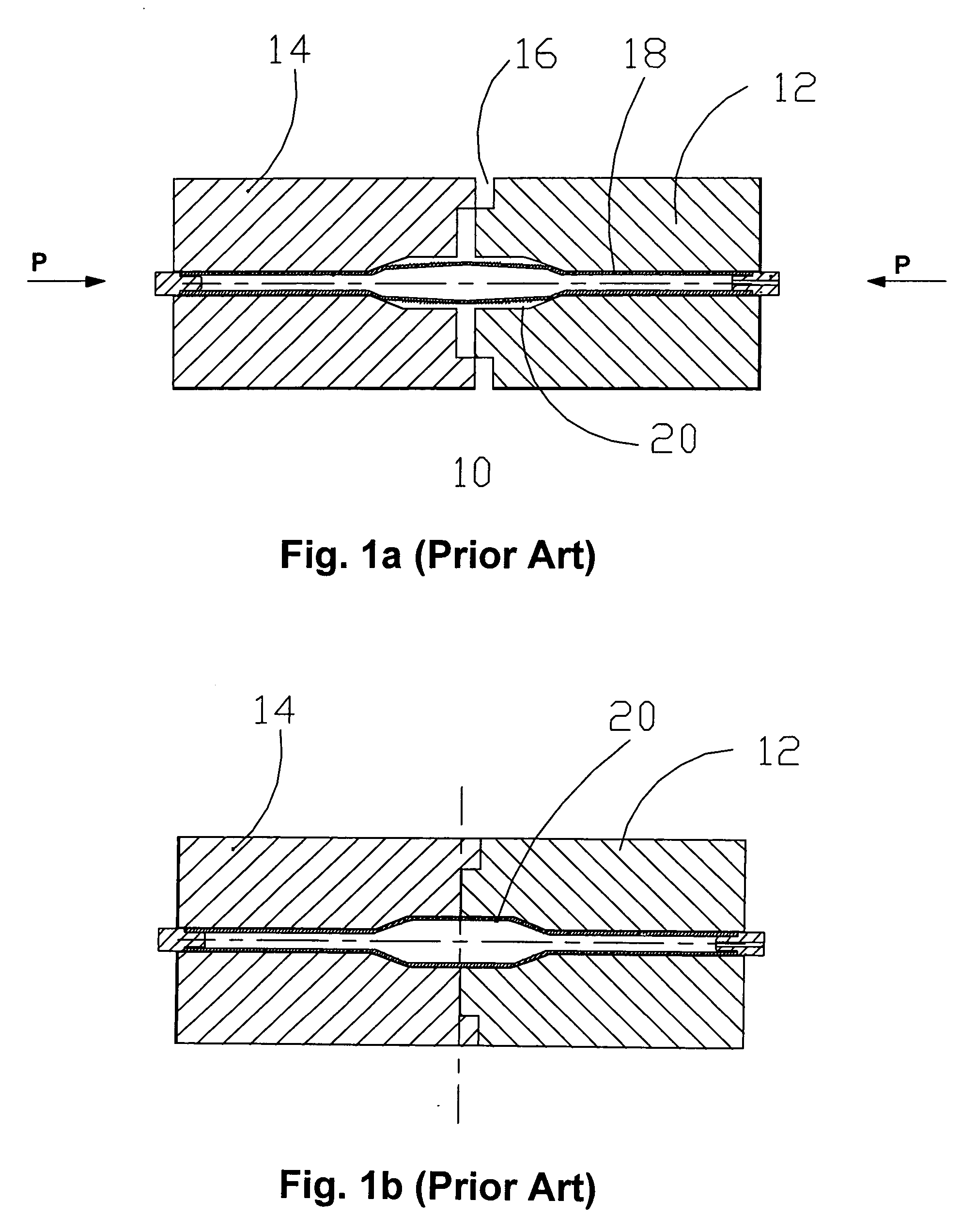
[0018]FIG. 1 shows a hydroforming die set 10 which is composed of two sections, 12 and 14. As in the prior art, the die 10 is intended to separate at 16 for work removal etc.

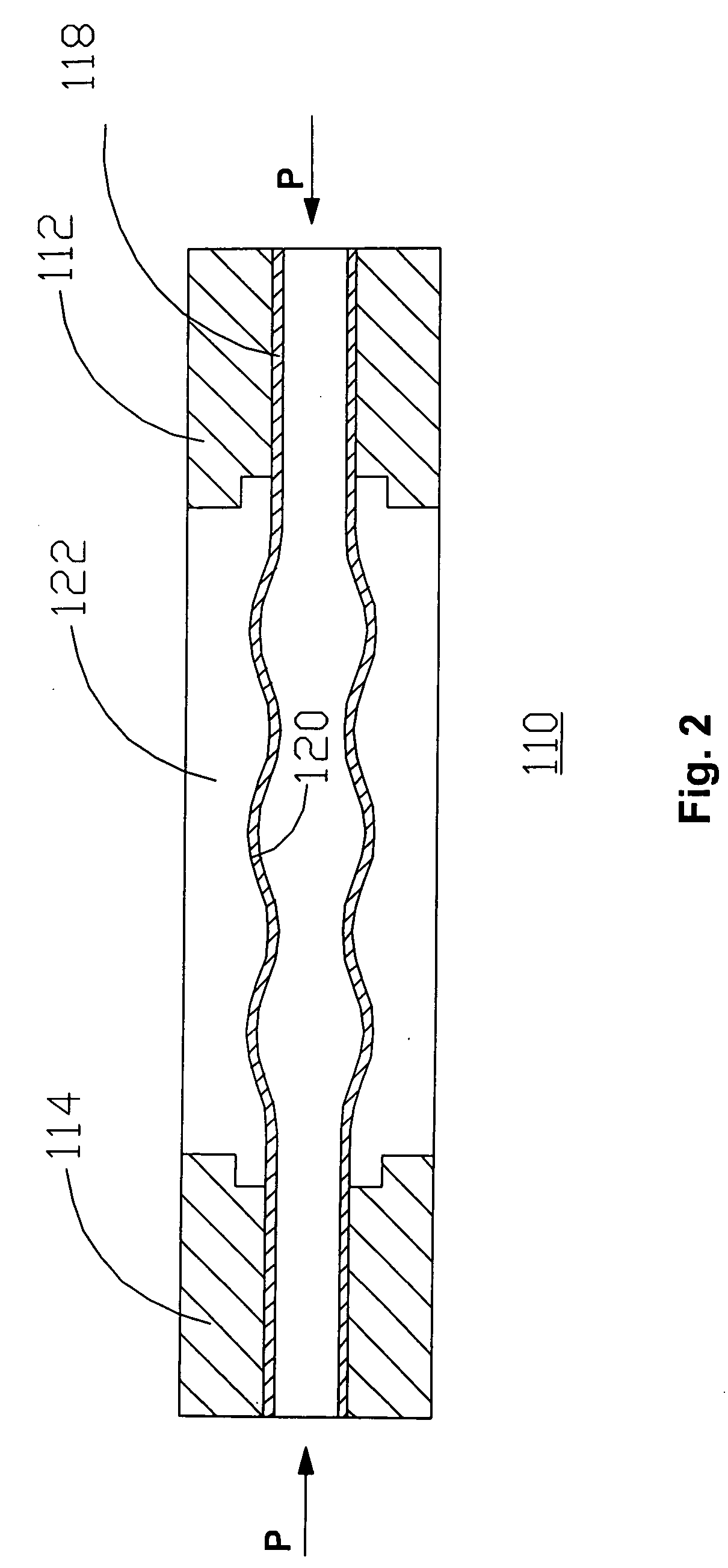
[0019] A tube 18 is inserted into die 10 to be hydroformed in recess 20. A small gap 16 is left between die sets 12 and 14. In the usual hydroforming operation tube 18 is enlarged in chamber 20 merely by applying hydraulic pressure to the inside of tube 18. In this instance a compressive pressure P is also applied to the ends of tube 18. This puts the tube 18 in a suitable confinement for expansion when a suitable hydraulic force is applied to the interior of tube 18. Gradually the gap shown at 16 is reduced to zero as the tube expansion progresses and the compressive force P is continuously applied to the ends of tube 18.

[0020] Because of the previously applied force P, the tube 18 may now be formed into a predetermined shape without substantial wall thinning as would be present in the absence of the pressure...


PUM

PropertyMeasurementUnit
compressive forceaaaaaaaaaa
yield pointaaaaaaaaaa
shapeaaaaaaaaaa

Abstract

It has been found that a compressive force assists in obtaining desired cold flow characteristics of a tubular steel work piece during a hydroforming operation. It has also been found that the most desirable results are achieved when the compressive force applied to the ends of the tubular steel work piece is just slightly less than the force that drive the tubular steel work piece into its yield point. A work piece previously formed by the above mentioned hydroforming operation may now be bent and subjected to a secondary hydroforming operation to produce a bent hydroformed tubular steel finished work piece having complex geometry.

Description

[0001] This application is an improvement over U.S. Pat. No. 6,912,884. BACKGROUND OF THE INVENTION [0002] U.S. Pat No. 6,912,884 describes a method of hydroforming tubular objects which overcomes some of the problems of the prior art. For instance, where tubing is expanded by mechanical means, the problem of localized tube wall thinning is a persistent problem. The above patent provides a method of hydroforming a tube having enlarged sections where the enclosing die set is manipulated to undergo controlled movement so as to reduce the wall thinning phenomena during a hydroforming operation. This is often accomplished by controlled die movement and applying compressive force to the work piece whilst a hydroforming operation is taking place. SUMMARY OF THE INVENTION [0003] It has been found that the material of the work product may be made to “cold flow” in a predetermined manner by altering. the pressure applied to the ends of the tube before hydroforming pressure is applied. If the...

Claims


Application Information

Patent Timeline
Patent Type & Authority Applications(United States)
IPC IPC(8): B21D26/02
CPCB21D26/055
Inventor GHARIB, MOHAMED
Owner GHARIB MOHAMED
Learn More