System and method for intercepting a projectile

a projectile and projectile technology, applied in the field of system and method for intercepting a projectile, can solve the problems of destroying the property located within the debris field, unable to solve the problem of intercepting the deflected missile, and putting people in danger of life and property,

Inactive Publication Date: 2007-07-26
SCV QUALITY SOLUTIONS
View PDF13 Cites 43 Cited by
  • Summary
  • Abstract
  • Description
  • Claims
  • Application Information

AI Technical Summary

Problems solved by technology

However, the THAAD system leaves a debris field 118 on the earth's surface 122 risking property and life.
However, after the missile 104 is destroyed, debris will fall to the earth's surface 122 landing in an area referred to as a debris field 122, thereby risking damage to property located within the debr

Method used


Image

  • System and method for intercepting a projectile
  • System and method for intercepting a projectile
  • System and method for intercepting a projectile

Examples


Embodiment Construction

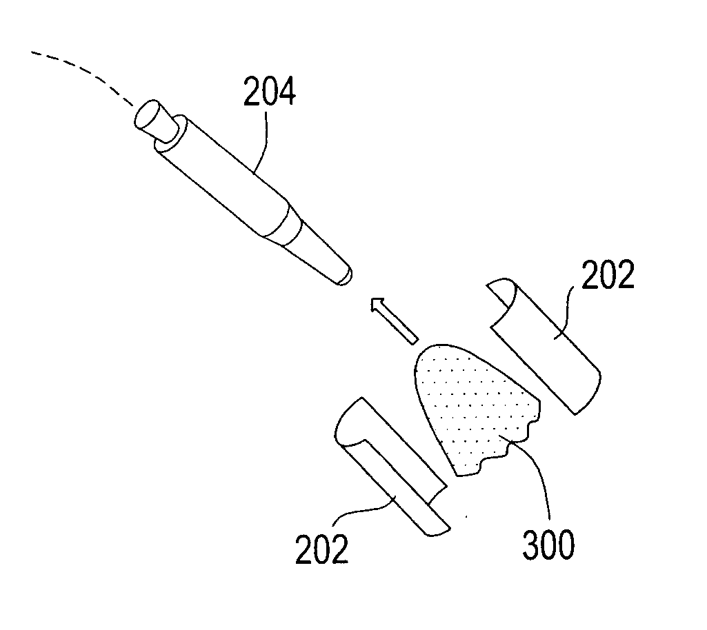
[0031] Embodiments of the present disclosure generally pertain to systems and methods for intercepting projectiles, e.g., mortar rounds and missiles. A projectile interception system in accordance with at least one embodiment of the present disclosure contains debris from an intercepted missile in order to reduce the risks associated with the debris falling to earth.

[0032] In this regard, when a projectile is fired, the system detects the incoming projectile and launches a containing blanket. The containing blanket is fired in a direction and at a velocity to intercept the projectile. Furthermore, upon striking the projectile, the blanket envelops the projectile and activates a collapsible device that retards descent of the contained projectile.

[0033] An exemplary embodiment of the present disclosure is now described with reference to FIGS. 2-7. FIGS. 2-7 illustrate a sequential progression of the detection, interception, and containment of a projectile in accordance with an embod...


PUM


Abstract

A system has a containment blanket. The system further has a launcher configured to launch the containment blanket and logic configured to deploy the containment blanket. The containment blanket is configured to encompass an incoming projectile.

Description

RELATED ART [0001] There are systems in use or in development for intercepting intercontinental ballistic missiles (ICBMs), shoulder-launched rockets, and / or rocket-propelled grenades (RPGs). Such systems are now described with reference to FIG. 1A-FIG. 1C. [0002] Generally, FIG. 1A illustrates a ground-based launch site 102 situated on the earth's surface 122 from which a missile 104 is launched. There are a variety of ways known in the art for detecting the incoming missile. For example, FIG. 1A further illustrates a satellite 108, an early warning system 132, and a command, control, and communications (CCC) base 141. [0003] The satellite 108 may detect the launch of the missile 104 from the launch site 102. Further, the early warning system 132 may detect, via radar, the missile 104. The satellite 108 and the early warning system 132 then transmits data to the CCC base 141 indicative of the location of the launch, the velocity of the missile, and other data indicative of the traj...

Claims


Application Information

Patent Timeline
IPC IPC(8): F41F5/00
CPCF41H13/0006F41H11/02
Inventor VICKROY, SAMUEL C.
Owner SCV QUALITY SOLUTIONS
Why Eureka
Try Eureka