Thermoacoustic thermomagnetic generator

Inactive Publication Date: 2007-08-02
FELLOWS OSCAR L
View PDF15 Cites 19 Cited by
  • Summary
  • Abstract
  • Description
  • Claims
  • Application Information

AI Technical Summary

Problems solved by technology

The application of heat causes the keeper to transition between magnetic and non-magnetic states, and temporarily lose its ability to conduct magnetic lines of force, thereby opening the magnetic circuit.

Method used


Image

  • Thermoacoustic thermomagnetic generator
  • Thermoacoustic thermomagnetic generator
  • Thermoacoustic thermomagnetic generator

Examples


Embodiment Construction

[0023] The present invention is a method and apparatus for a thermoacoustic thermomagnetic generator. This disclosure describes numerous specific details in order to provide a thorough understanding of the present invention. One skilled in the art will appreciate that one may practice the present invention without these specific details. Additionally, this disclosure does not describe some well known items in detail in order not to obscure the present invention.

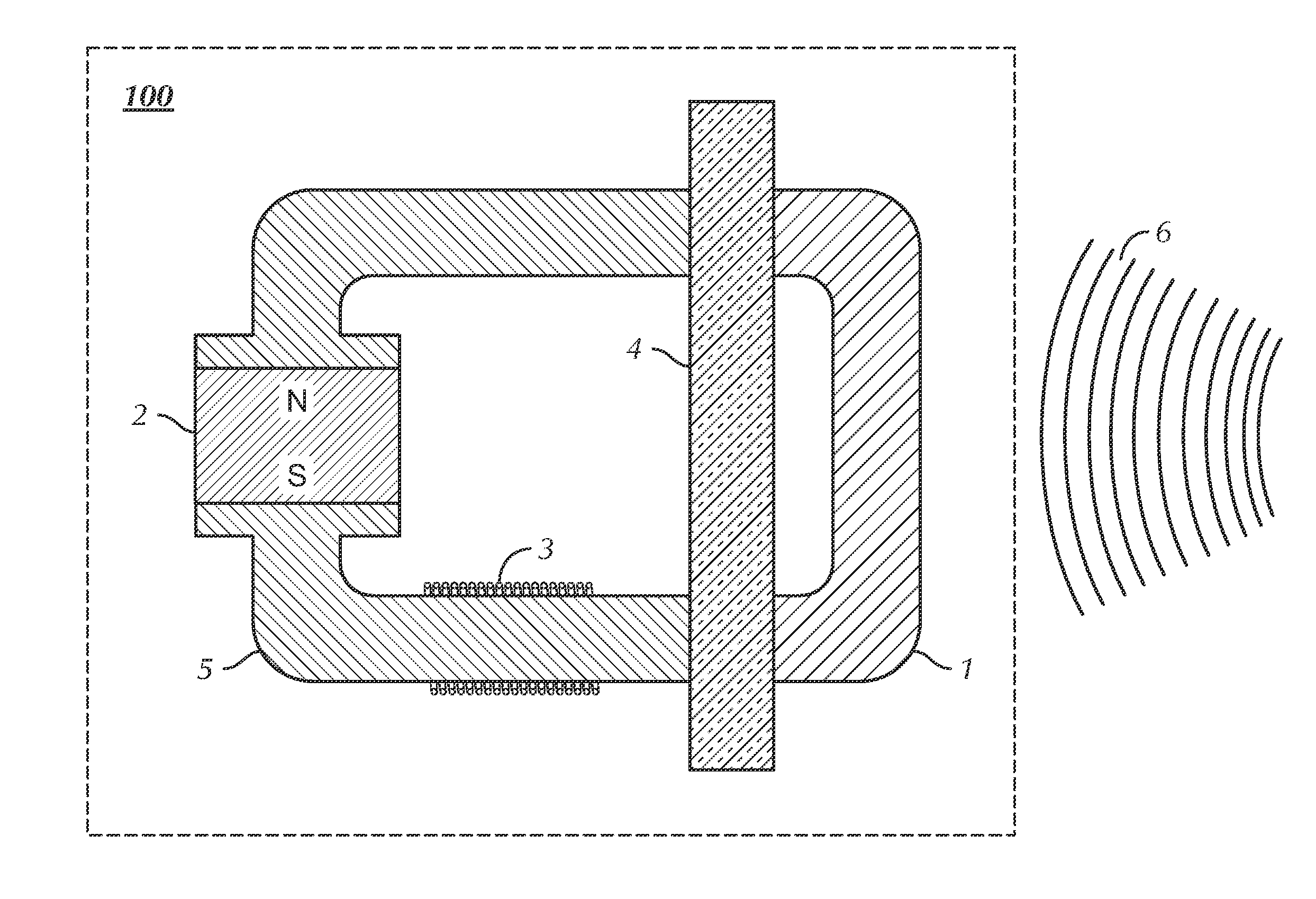
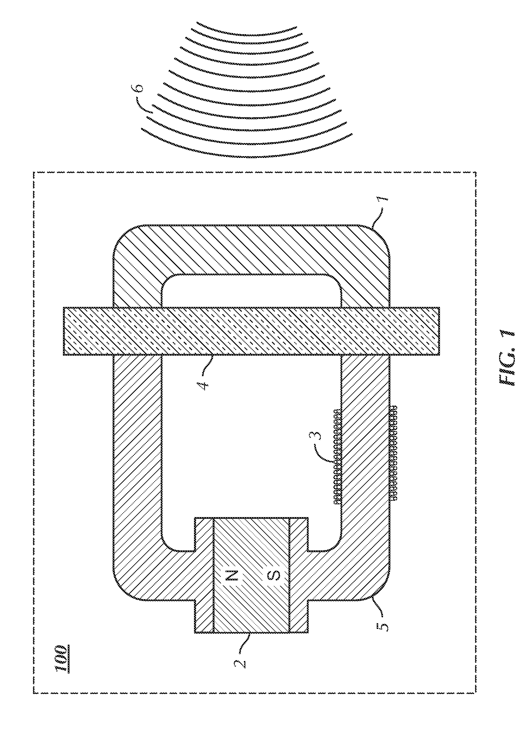
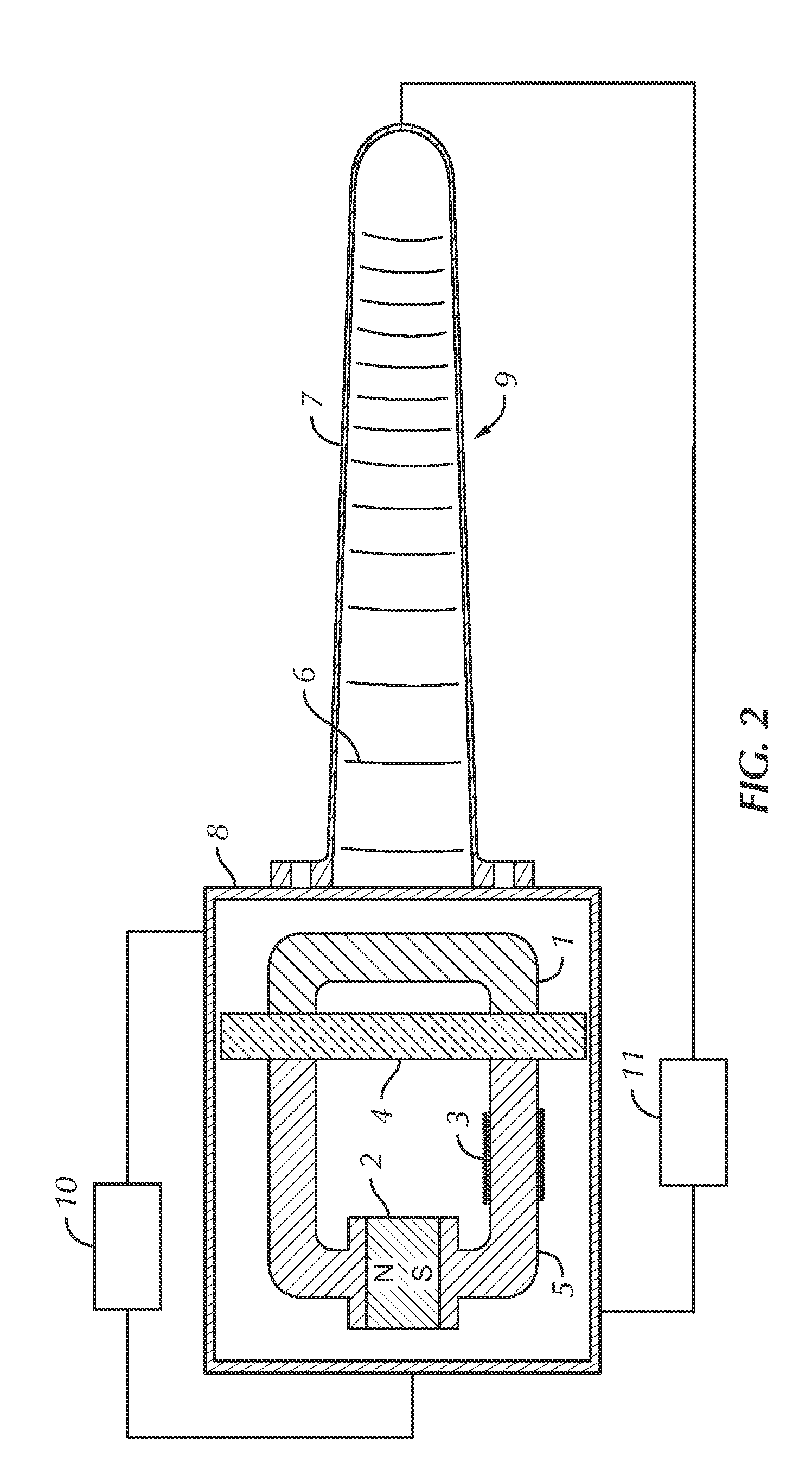
[0024] The present invention is a major operational component of a thermoacoustic engine such as describe in the Thermoacoustic Resonator Patent and the Thermoacoustic Engine Patent. To fully appreciate the novelty of the present invention, I make reference to the operation of the present invention as used in an exemplary thermoacoustic engine as previously described and illustrated in those patents. A thermoacoustic engine generates an acoustic wave that transports thermal energy. There is a thermal gradient between the nod...


PUM


Abstract

The present invention is a thermoacoustic thermomagnetic generator 100. The generator includes a stator 5 that supports and channels magnetic fields. It further includes a magnetic field generator 2 that magnetically couples to the stator. In addition, the generator includes a magnetic circuit opening and closing member 1 that changes magnetic states in response to changes in temperature where the member couples to the stator to complete a magnetic circuit. Further, the generator includes a thermal insulator 4 that couples to the stator and the magnetic circuit opening and closing member. And, the generator includes a plurality of induction windings 3 that conduct electric current where the induction windings couple to the stator. The periodic opening and closing of the magnetic circuit creates a magnetic field in the stator that induces an alternating electric current in the induction windings which allows the generator to produce electric power.

Description

CROSS REFERNECE TO RELATED APPLICATIONS [0001] This application is a continuation of U.S. patent application Ser. No. 10 / 908,711, filed May 24, 2005, which is incorporated by reference for all purposes into this specification.BACKGROUND OF THE INVENTION [0002] 1. Field of the Invention [0003] The present invention relates to thermoacoustic generators. More specifically, the present invention relates to thermoacoustic thermomagnetic generators. [0004] 2. Description of the Related Art [0005] The first record known of a thermo-magnetic motor making use of the Curie point property of materials is the Nikola Tesla patent, U.S. Pat. No. 396,121. In his patent, Dr. Tesla describes a kinematic thermo-magnetic motor in which a mechanism is caused to reciprocate by means of interrupting a magnetic circuit by the periodic application of heat to a metal “keeper” component that completes the magnetic circuit. The application of heat causes the keeper to transition between magnetic and non-magne...

Claims


Application Information

Patent Timeline
Patent Type & Authority Applications(United States)
IPC IPC(8): F01K13/00
CPCH01L37/04H10N15/20
Inventor FELLOWS, OSCAR L.
Owner FELLOWS OSCAR L
Why Eureka
Try Eureka