Electric shift transfer case

Inactive Publication Date: 2007-08-02
BORG WARNER INC
View PDF17 Cites 15 Cited by
  • Summary
  • Abstract
  • Description
  • Claims
  • Application Information

AI Technical Summary

Benefits of technology

[0006] Another improvement to the current design that the present invention provides will be the use of sensors that can detect the position of the dog clutch. The dog clutch is the device that, depending upon its position along the output shaft, will provide either a direct drive, or a reduced speed gear ratio. Current designs of the transfer case use the position of a bidirectional motor, which is the device that controls the shift, to detect

Problems solved by technology

Because of possible lag in the shift, the position of the bidirectio

Method used


Image

  • Electric shift transfer case
  • Electric shift transfer case

Examples


Example

[0013] The following description of the preferred embodiment(s) is merely exemplary in nature and is in no way intended to limit the invention, its application, or uses.

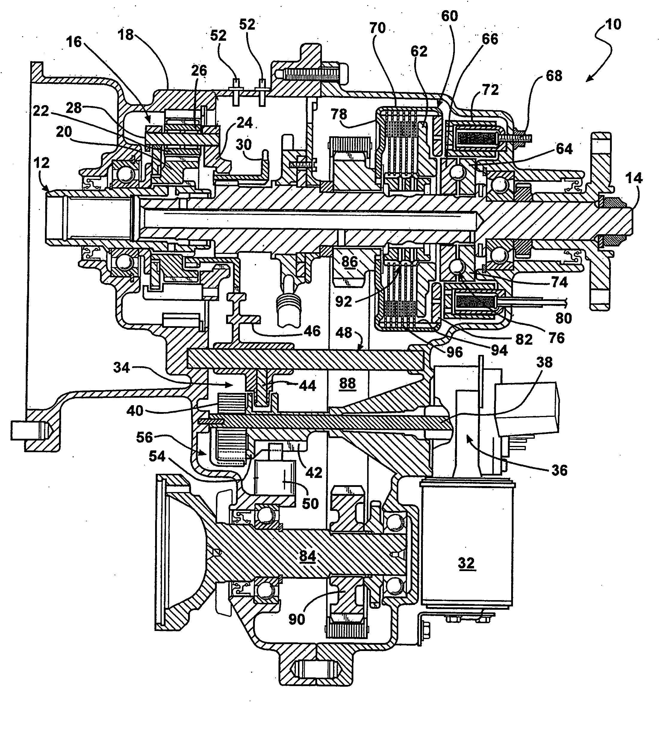
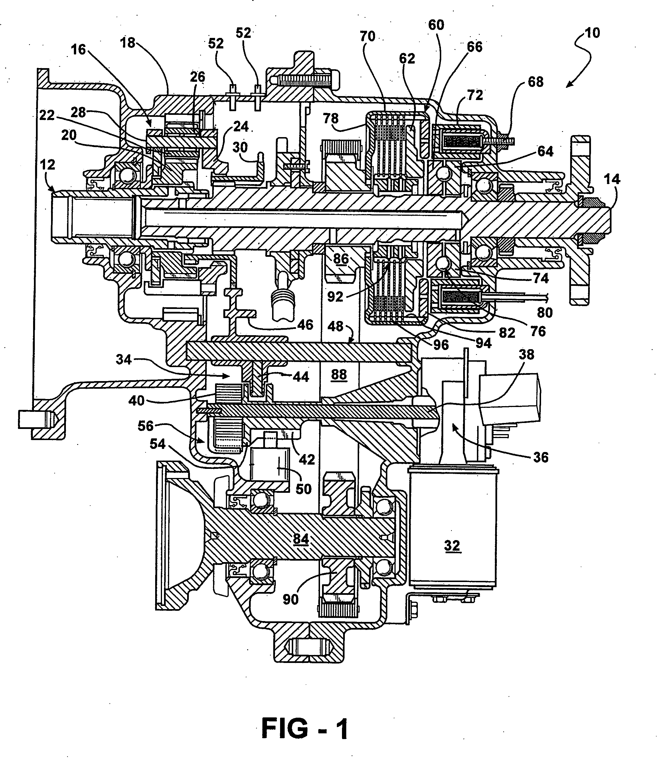
[0014] Referring to FIG. 1, a transfer case that has the present invention is shown at 10. The transfer case 10 includes a casing 18 which includes various supports, bearing surfaces, threaded openings, and other various features that serve the purpose of receiving other components of the transfer case. Among the other components is a gear reduction set 16 that is driven by the input shaft 12 and is coupled with the output shaft 14. The input shaft 12 has a plurality of teeth that are splined with the teeth on the internal surface of the sun gear 20. The sun gear 20 also has a plurality of teeth on its external surface that are in mesh with the planetary gears 22. The planetary gears 22 are rotatably received on stub shafts 28, which are mounted onto carrier 24. The ring gear 26 has a plurality of teeth that are dir...


PUM


Abstract

A shift fork restrictor operably disposed in a transfer case for the purpose of allowing the shift motor to transfer energy to the currently existing double wound spring, where the energy is stored until the shift motor sensor indicates that the motor is in the proper range location. When the motor is in the proper range location, the stored energy in the spring is released by the shift fork restrictor releasing the cam allowing for maximum torque and speed to be provided through the secondary rail, cam, and shift fork to complete the requested range shift. This configuration can be used to, among other things, select a high or low range in the transfer case, as well as couple the input and output shafts together, which have different gear ratios.

Description

CROSS-REFERENCE TO RELATED APPLICATIONS [0001] This application claims the benefit of U.S. Provisional Application No. 60 / 762,680, filed Jan. 27, 2006. The disclosure of the above applications is incorporated herein by reference.FIELD OF THE INVENTION [0002] The present invention relates to a shift restrictor apparatus for a transfer case. BACKGROUND OF THE INVENTION [0003] This invention relates generally to the operation of two-speed transfer cases and more specifically to the shift from high to low range. It is known in the automobile industry that most vehicles that use either four-wheel-drive or all-wheel-drive systems are equipped with some sort of device for transferring power to the front wheels, usually this device is a transfer case, or something similar. [0004] Current designs of the transfer case involve the use of a planetary gear set to obtain different gear ratios between the input shaft and output shaft of the transfer case. To change gear ratios, a shift system havi...

Claims


Application Information

Patent Timeline
IPC IPC(8): F16H61/00F16H63/32
CPCF16H63/304F16H63/34Y10T74/20183F16H2063/3063Y10T74/19251F16H2063/3089
Inventor OLIVEIRA, GARYTUBBS, FREDRIC HAROLD
Owner BORG WARNER INC
Why Eureka
Try Eureka