Bicycle shifting method

a shifting method and bicycle technology, applied in the field of bicycle shifting method, can solve the problems of affecting the pedaling action of the rider, the operation of the front and rear derailleurs to move the chain in a large amount, and the rider's pedaling action is not smooth, so as to reduce the possibility of shifting parts being damaged, and the effect of ensuring riding comfor

Active Publication Date: 2014-04-29
GIANT MFG
View PDF2 Cites 14 Cited by
  • Summary
  • Abstract
  • Description
  • Claims
  • Application Information

AI Technical Summary

Benefits of technology

[0008]The invention is directed to a bicycle shifting method to guarantee the riding comfort and reduce possible damages to shifting parts.
[0019]In view of the above, a bicycle shifting method suitable for controlling a gear ratio of a bicycle is provided. According to the bicycle shifting method, the controller storing the gear-ratio table controls the front electronic derailleur, the rear electronic derailleur, or both of the front electronic derailleur and the rear electronic derailleur based on the signal generated by triggering the controlling switch, so as to increase the gear ratio along the speed-increasing path of the gear-ratio table or decrease the gear ratio along the laborsaving path of the gear-ratio table. Note that the speed-increasing path is different from the laborsaving path. By applying the bicycle shifting method, possible damages to shifting parts during the shifting operation of the bicycle may be reduced, and the riding comfort may be guaranteed.

Problems solved by technology

Said operation is rather complicated.
At this time, if the adjustment of the gear ratio requires the simultaneous change to the locations of the chain on the front and rear chain rings, the repetitive changing actions may cause the front and rear derailleurs to move the chain to a great extent.
Thereby, the rider's pedaling action is not smooth, and the shifting parts are likely to be damaged.

Method used


Image

  • Bicycle shifting method
  • Bicycle shifting method
  • Bicycle shifting method

Examples


Embodiment Construction

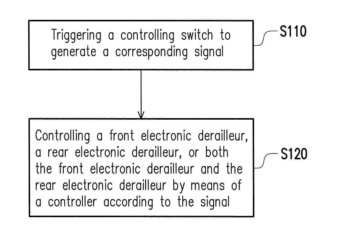
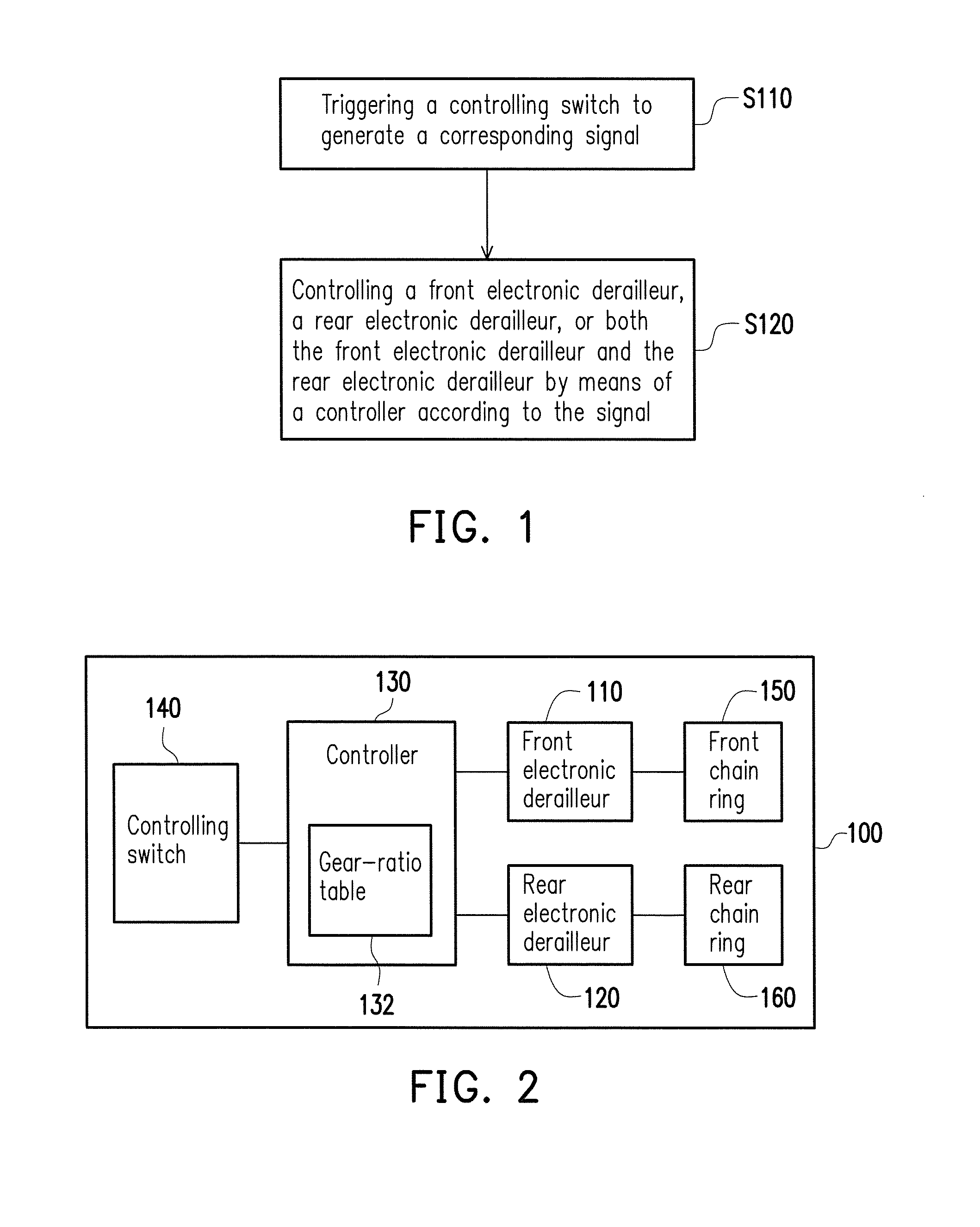
[0028]FIG. 1 is a flow chart illustrating a bicycle shifting method according to an embodiment of the invention. With reference to FIG. 1, in the present embodiment, the bicycle shifting method includes following steps. In step S110, a controlling switch is triggered to generate a corresponding signal. In step S120, a front electronic derailleur, a rear electronic derailleur, or both of the front electronic derailleur and the rear electronic derailleur are controlled by a controller according to the signal. Accordingly, the bicycle shifting method is suitable for controlling a gear ratio of a front chain ring and a rear chain ring of the bicycle.

[0029]FIG. 2 is a schematic diagram of a bicycle according to an embodiment of the invention. With reference to FIG. 2, in the present embodiment, the bicycle 100 has a front electronic derailleur 110, a rear electronic derailleur 120, a controller 130, and a controlling switch 140. The controller 130 stores a gear-ratio table 132. Hence, th...


PUM


Abstract

A bicycle shifting method suitable for controlling a gear ratio of a front chain ring and a rear chain ring of the bicycle is provided. The bicycle has a front electronic derailleur, a rear electronic derailleur, a controller, and a controlling switch, and the controller stores a gear-ratio table. The bicycle shifting method includes following steps. The controlling switch is triggered to generate a corresponding signal. One or both of the electronic derailleurs are controlled by the controller according the signal. When the signal is a speed-increasing signal, the controller controls the electronic derailleurs to increase the gear ratio along a speed-increasing path of the gear-ratio table. When the signal is a laborsaving signal, the controller controls the electronic derailleurs to decrease the gear ratio along a laborsaving path of the gear-ratio table. The speed-increasing path is different from the laborsaving path.

Description

CROSS-REFERENCE TO RELATED APPLICATION[0001]This application claims the priority benefits of Taiwan application serial no. 101134924, filed on Sep. 24, 2012. The entirety of the above-mentioned patent applications is hereby incorporated by reference herein and made a part of this specification.BACKGROUND OF THE INVENTION[0002]1. Field of the Invention[0003]The invention relates to a shifting method and particularly to a bicycle shifting method.[0004]2. Description of Related Art[0005]In recent years, the market for bicycles has been growing, and thus consumers are not only interested in the recreational road bicycles but also fond of the high-end racing bicycles. Generally, the bicycles are equipped with derailleurs, so as to move the chain onto different chain rings according to different terrain requirements and various consumers' needs. The derailleurs include front and rear derailleurs respectively controlling the locations of the chain on the front and rear chain rings. Due to ...

Claims


Application Information

Patent Timeline
Patent Type & Authority Patents(United States)
IPC IPC(8): G06F7/00
CPCF16H61/26B62M25/08
Inventor LEE, KUN-HUI
Owner GIANT MFG
Why Eureka
Try Eureka