Percutaneously introduced blood pump and related methods

Inactive Publication Date: 2006-07-13
ABOUL HOSN WALID NAGIB
View PDF7 Cites 166 Cited by
  • Summary
  • Abstract
  • Description
  • Claims
  • Application Information

AI Technical Summary

Benefits of technology

[0031] Another object of the present invention comprises a method and device for reducing the left or right ventricle volume by the simultaneous use of the pumping system mentioned above in conjunction with injections of engineered or autologous tissue into the myocardium to help regenerate a healthy myocar

Problems solved by technology

Although generally advantageous for these reasons, among others, the percutaneously introduced blood pumps of the prior art nonetheless suffer from various drawbacks.
One drawback involves the potential for thrombus formation.
A still further drawback with prior art per

Method used


Image

  • Percutaneously introduced blood pump and related methods
  • Percutaneously introduced blood pump and related methods
  • Percutaneously introduced blood pump and related methods

Examples


Example

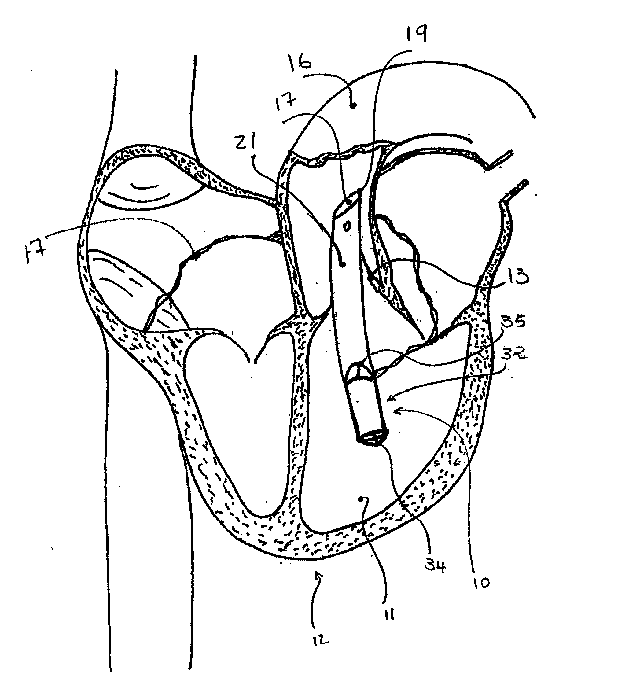
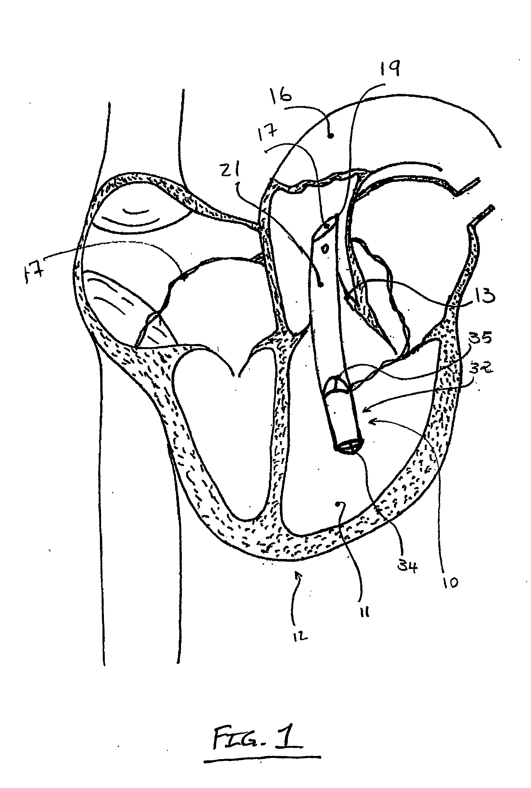
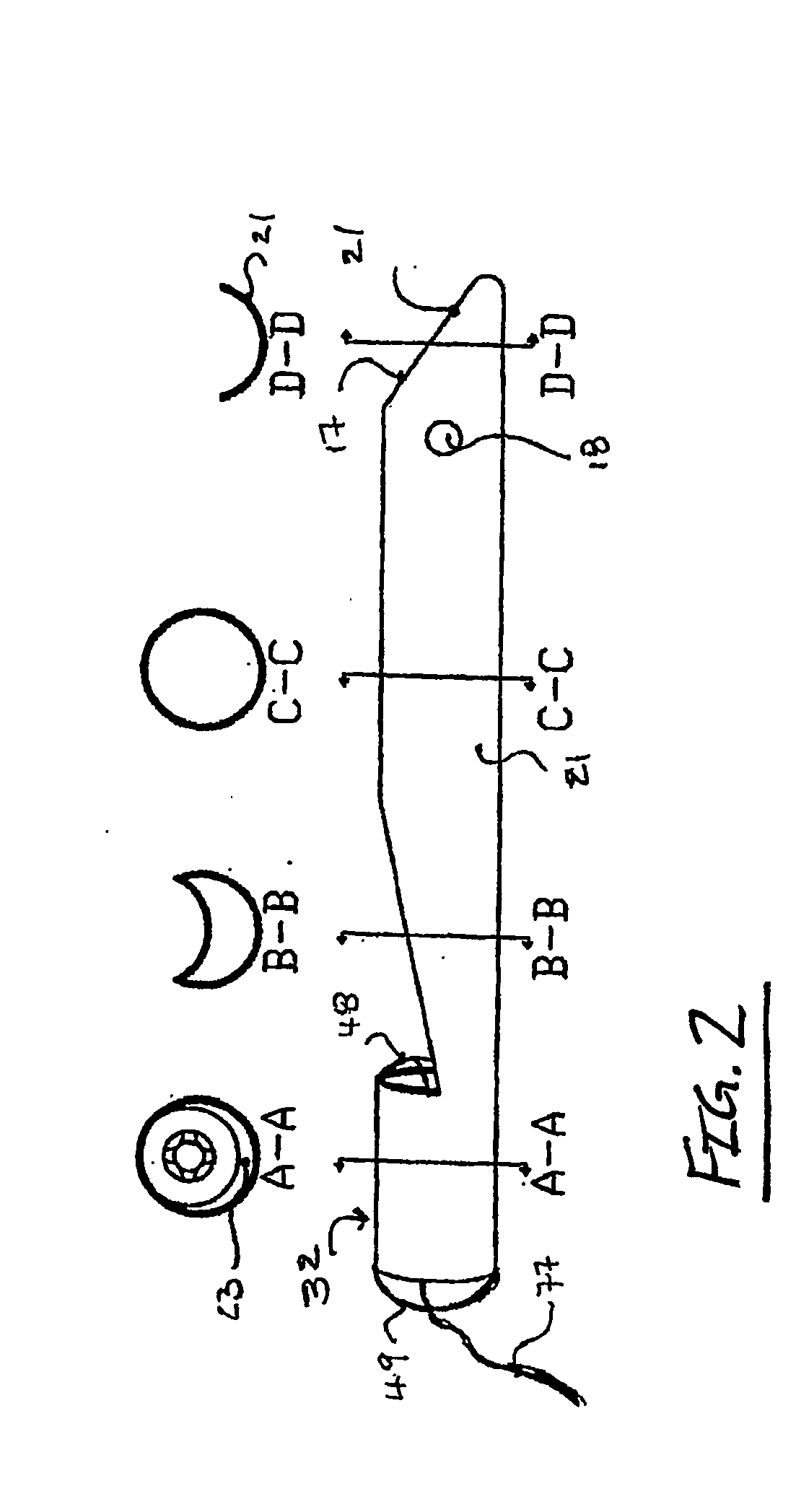
[0057] With reference to FIG. 2, a first embodiment of the present invention system 10 is shown (by way of example only) implanted in an ailing heart 12 with pump 32 positioned in the left ventricle 11 and outflow cannula 21 placed across the aortic valve 13 in the aorta 16. In accordance with the preferred embodiment of the present invention, and with particular attention being directed to FIGS. 2 and 3 of the drawings, the pump generally designated 32 comprises a housing 36, the interior of which defines pumping chamber 37. Pump 32 having dual inlets, distal inlet 34 and proximal inlet 35, and an outflow cannula 21 to provide a conduit for blood energized by pump 32 to cross from the left ventricle 11 into aorta 16 across aortic valve 13. Pump 32 is preferably a centrifugal rotary pump; although either an axial type or a centrifugal type could be interchanged. In either case, pump 32 is sufficiently small to be implanted percutaneously through a main artery or vein such as the fem...


PUM


Abstract

The present invention involves a blood pump having a pump housing with an internally disposed rotor that collectively provide a dual inflow capability which prevents thrombus formation and reduces hemolysis during use.

Description

CROSS-REFERENCES TO RELATED APPLICATIONS [0001] The present application is an International Patent Application of and claims the benefit of priority from commonly owned and co-pending U.S. Provisional Patent Application Ser. Nos. 60 / 388,138 (filed Jun. 11, 2002) and 60 / 431,174 (filed Dec. 4, 2002), the entire contents of which are hereby expressly incorporated by reference into this disclosure as if set forth fully herein.BACKGROUND OF THE INVENTION [0002] I. Field of the Invention [0003] The present invention relates generally to a system for assisting the heart and, more particularly, to a pumping system and related method for supplementing the circulation of blood through the patient using a minimally invasive procedure. [0004] II. Description of Related Art [0005] Over the years, various types of percutaneously introduced blood pumps have been developed for the purpose of augmenting or replacing the blood pumping action of damaged or diseased hearts. Such blood pumps may be posi...

Claims


Application Information

Patent Timeline
IPC IPC(8): A61M1/12A61M1/10F04D3/02F04D13/06F04D29/04F04D29/048
CPCA61M1/101A61M1/12F04D3/02F04D13/0646F04D29/048A61M1/1015A61M1/1036A61M1/125A61M2205/3334A61M60/82A61M60/422A61M60/419A61M60/135A61M60/148A61M60/232A61M60/546A61M60/523A61M60/178A61M60/825
Inventor ABOUL-HOSN, WALID NAGIB
Owner ABOUL HOSN WALID NAGIB
Why Eureka
Try Eureka