Suspension system for vehicle

a suspension system and vehicle technology, applied in the direction of resilient suspensions, interconnection systems, liquid based dampers, etc., can solve the problems of reducing the road-holding ability of the vehicle, affecting the vibration damping control of the sprung-portion displacement force generator, etc., and achieves low speed ratio, low positive/negative efficiency product, and low speed ratio of the speed reducer of the actuator

Inactive Publication Date: 2012-08-14
TOYOTA JIDOSHA KK
View PDF23 Cites 13 Cited by
  • Summary
  • Abstract
  • Description
  • Claims
  • Application Information

AI Technical Summary

Benefits of technology

[0017]In the suspension system according to this mode (1), the displacement force generated by the displacement force generator is caused to act as the damping force against the sprung-portion vibration, for thereby executing the sprung-portion vibration damping control. Since the hydraulic damper, which is disposed in parallel with the displacement force generator, is configured to generate the hydraulic damping force acting against displacement of the sprung and unsprung portions relative to each other, the hydraulic damping force could act on the sprung-portion vibration, so that there is a risk that the hydraulic damping force would affect the sprung-portion vibration damping control executed by the displacement force generator. In view of such a risk, it is desirable to minimize the hydraulic damping force upon execution of the sprung-portion vibration damping control. However, where the hydraulic damping force is reduced by taking account of the influence of the hydraulic damping force affecting the sprung-portion vibration, the hydraulic damping force would less affect unsprung-portion vibration (which occurs in the unsprung portion) as well as the sprung-portion vibration, thereby reducing effect of damping the unsprung-portion vibration so that there is a risk that the road-holding ability of the vehicle could be reduced. The road-holding ability would be reduced with reduction of the hydraulic damping force, particularly, upon occurrence of vibrations of relatively high frequency range.
[0043]In the system according to this mode (11), the speed ratio of the speed reducer of the actuator is relatively low, namely, a ratio of an actuation amount of the actuator to a motion amount of the electromagnetic motor is relatively low. It can be considered that the above-described positive / negative efficiency product is, in general, reduced by employing the speed reducer having a low speed ratio. In view of this, the system of this mode can be considered as a kind of the system in which the actuator having a relatively low positive / negative efficiency product is employed. The employment of the speed reducer having the low speed ratio permits the electromagnetic motor to be made compact in size.

Problems solved by technology

Since the damping force generated by the hydraulic damper (hereinafter referred to as “hydraulic damping force” where appropriate, so as to be distinguished from the displacement force which is generated by the displacement force generator and which acts as the damping force against the sprung-portion vibration) is caused to act against the displacement of the sprung and unsprung portions relative to each other, there is a risk that the sprung-portion vibration damping control executed by the displacement force generator would be affected by influence of the hydraulic damping force generated by the hydraulic damper.
However, as described later in detail, since the hydraulic damping force correlates closely with road-holding ability of the vehicle, there is a risk that reduction of the hydraulic damping force would lead to reduction of the road-holding ability of the vehicle, particularly, upon occurrence of vibrations of relatively high frequency range.

Method used


Image

  • Suspension system for vehicle
  • Suspension system for vehicle
  • Suspension system for vehicle

Examples


first embodiment

(A) First Embodiment

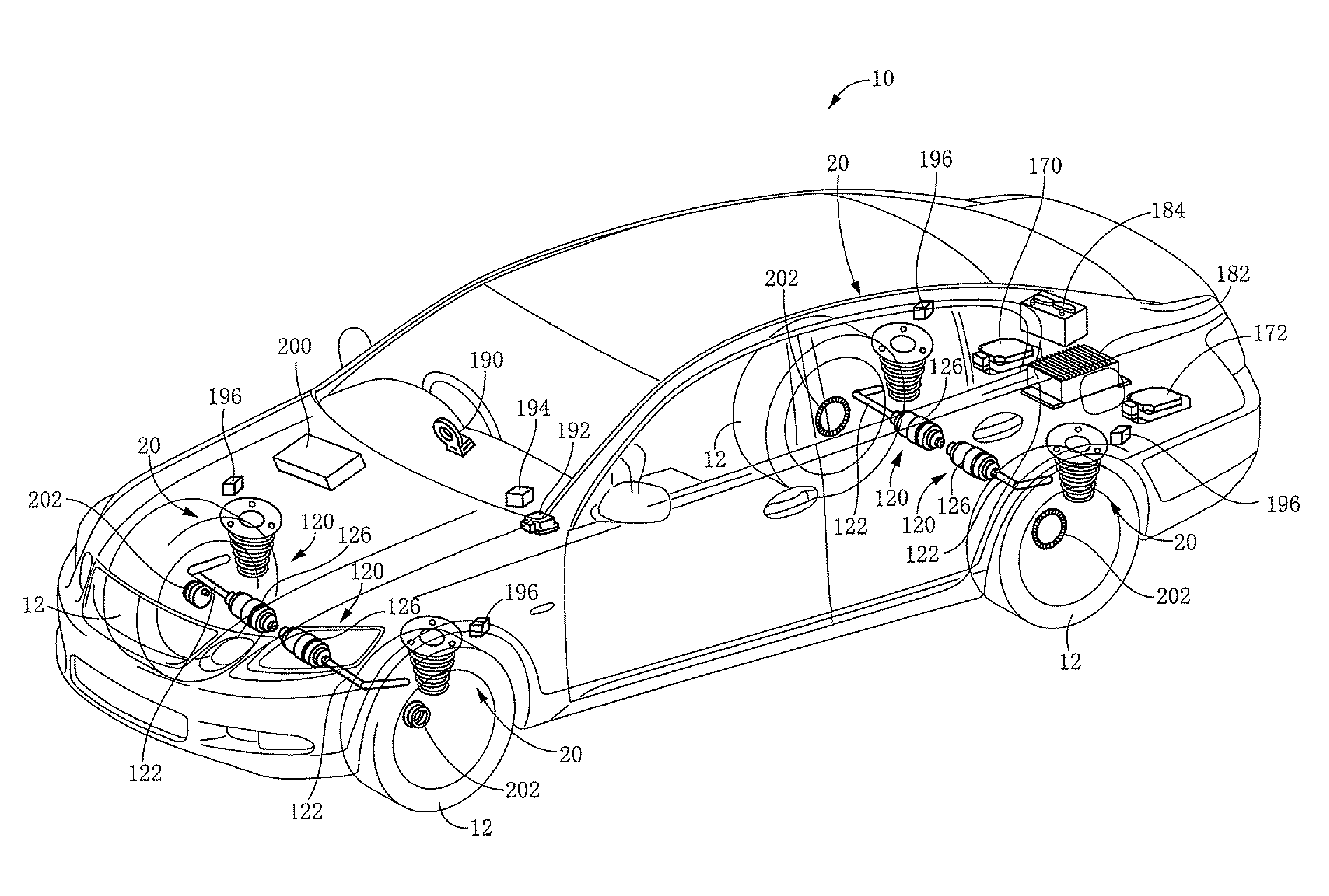
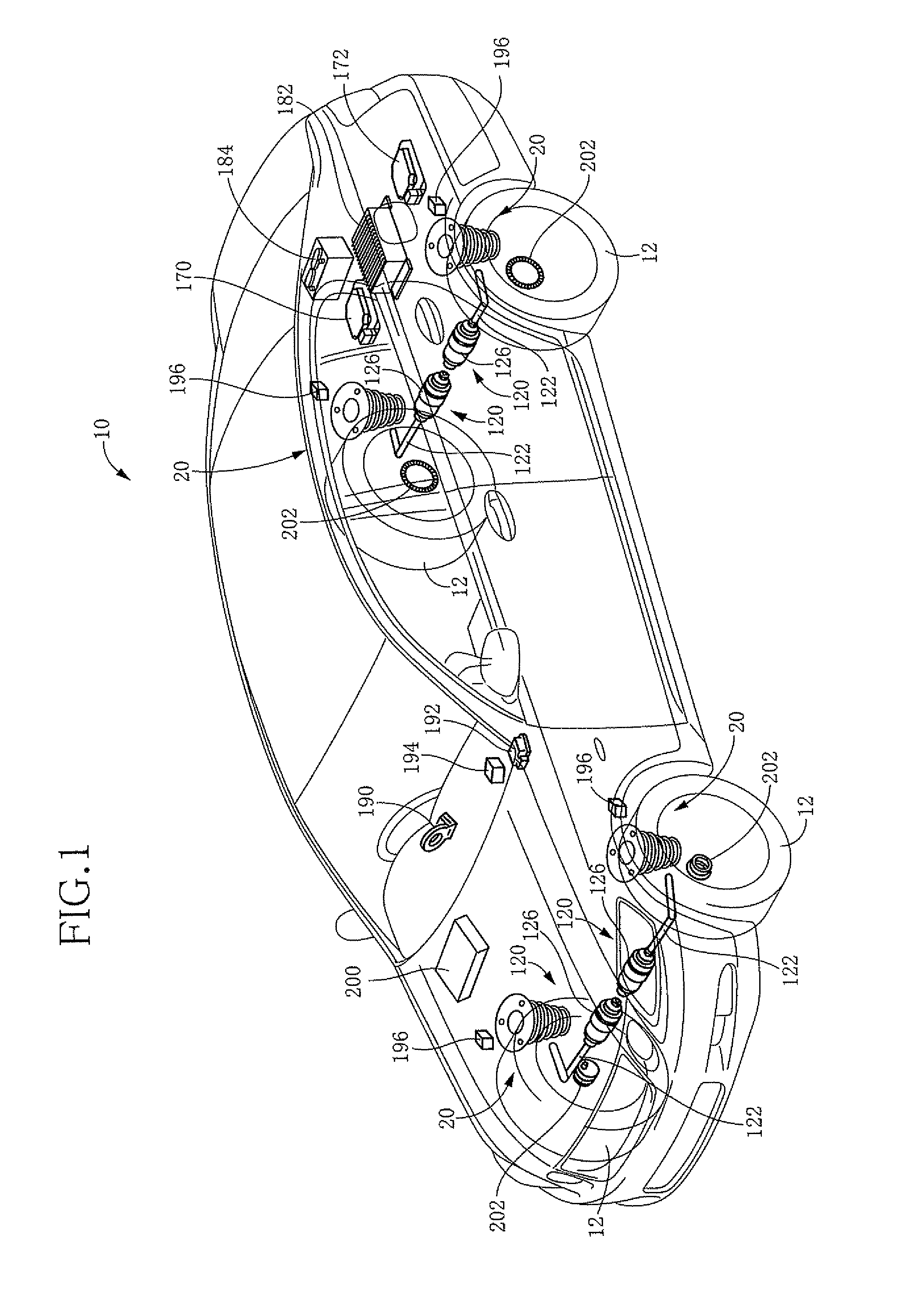
[0064]FIG. 1 schematically shows a vehicle suspension system 10, which includes four suspension devices 20 that are provided for respective four wheels 12 (i.e., front right, front left, rear right and rear left wheels 12) and a controller device configured to control the suspension devices 20. Each of the suspension devices 20 provided for a front wheel 12 as a steered wheel is equipped with a mechanism for allowing the wheel 12 to be steered, while each of the suspension devices 20 provided for a rear wheel 12 as a non-steered wheel is not equipped with such a steering mechanism. However, since all the suspension devices 20 can be regarded to be identical in construction with one another except for presence or absence of the steering mechanism, there will be described, as a representative of the four suspension devices 20, one of the suspension devices 20 that is provided for the rear wheel 12, in the interest of simplification of the description.

[0065]As shown...

second embodiment

(B) Second Embodiment

[0115]FIG. 14 schematically shows a vehicle suspension system 230 that is constructed according to a second embodiment of the invention. The above-described suspension system 10 according to the first embodiment is equipped with the hydraulic dampers 56 of rotary type. However, the present suspensions system 230 is equipped with hydraulic dampers 232 of cylinder type. In the following description regarding the suspensions system 230, the same reference signs as used in the above-described suspension system 10 will be used to identify the functionally corresponding elements, and redundant description of these elements is not provided.

[0116]The suspension system 230 includes four suspension devices 234 that are provided for respective four wheels 12 (i.e., front right, front left, rear right and rear left wheels 12). As shown in FIG. 15, each suspension device 234 of independent type is provided by a multi-link suspension, and is equipped with an arm assembly as t...


PUM


Abstract

A suspension system for a vehicle, including: (a) a suspension spring; (b) a hydraulic damper; (c) a displacement force generator disposed in parallel with the suspension spring and the damper; and (d) a controller including a damping-force controlling portion for controlling a damping force of the damper and a displacement-force controlling portion for controlling a displacement force of the displacement force generator. The displacement-force controlling portion is configured to execute a sprung-portion vibration damping control for controlling the displacement force, such that the generated displacement force acts as a damping force against sprung-portion vibration. The damping-force controlling portion is configured, upon execution of the sprung-portion vibration damping control, to execute a damping force reducing control for reducing the damping force that is to be generated by the damper, depending on an intensity of unsprung-portion resonance frequency vibration which occurs in the vehicle and which has a resonance frequency of the unsprung portion.

Description

TECHNICAL FIELD[0001]The present invention relates to a suspension system for a vehicle, which is provided with a hydraulic damper and also a device including an electromagnetic motor and configured to generate, based on a force generated by the electromagnetic motor, a displacement force causing sprung and unsprung portions of the vehicle to be displaced toward or away from each other.BACKGROUND ART[0002]In recent years, there have been begun studies on a suspension system for a vehicle as disclosed in patent literatures as identified below, specifically, a system including a displacement force generator which includes an electromagnetic motor and which is provided in parallel with a suspension spring and a hydraulic damper. The displacement force generator is configured to generate, based on a force generated by the electromagnetic motor, a displacement force causing the sprung and unsprung portions to be displaced toward or away from each other, in a manner that enables the gener...

Claims


Application Information

Patent Timeline
Patent Type & Authority Patents(United States)
IPC IPC(8): B60G17/02
CPCB60G17/0157B60G17/018B60G17/08B60G21/0555F16F9/14B60G2200/18B60G2202/12B60G2202/22B60G2202/312B60G2202/42B60G2204/128B60G2204/129B60G2204/419B60G2400/102B60G2400/104B60G2400/106B60G2400/208B60G2400/41B60G2400/91B60G2800/012B60G2800/014B60G2800/916B60G2200/184
Inventor KAJINO, HIDENORI
Owner TOYOTA JIDOSHA KK
Why Eureka
Try Eureka