Driving force control device

A technology of control device and driving force, applied in the direction of transmission device, transmission device control, components with teeth, etc., can solve the problems such as the speed change shock of the continuously variable transmission, and achieve the effect of suppressing the shock

Inactive Publication Date: 2012-02-22
TOYOTA JIDOSHA KK
View PDF2 Cites 13 Cited by
  • Summary
  • Abstract
  • Description
  • Claims
  • Application Information

AI Technical Summary

Problems solved by technology

[0007] In the continuously variable transmission described in the above-mentioned Japanese Patent Application Laid-Open No. 2006-125602, if the gear ratio is changed stepwise as in the manual transmission mode described in the Japanese Patent Laid-Open No. 2006-112248, there will be a problem during the shifting process of the continuously variable transmission. Shift shock problem

Method used


Image

  • Driving force control device
  • Driving force control device
  • Driving force control device

Examples


Embodiment Construction

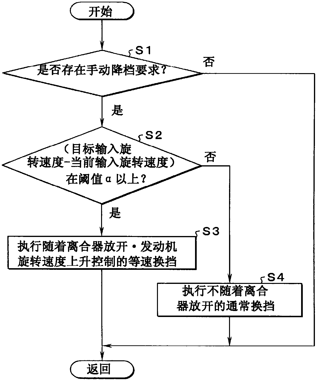
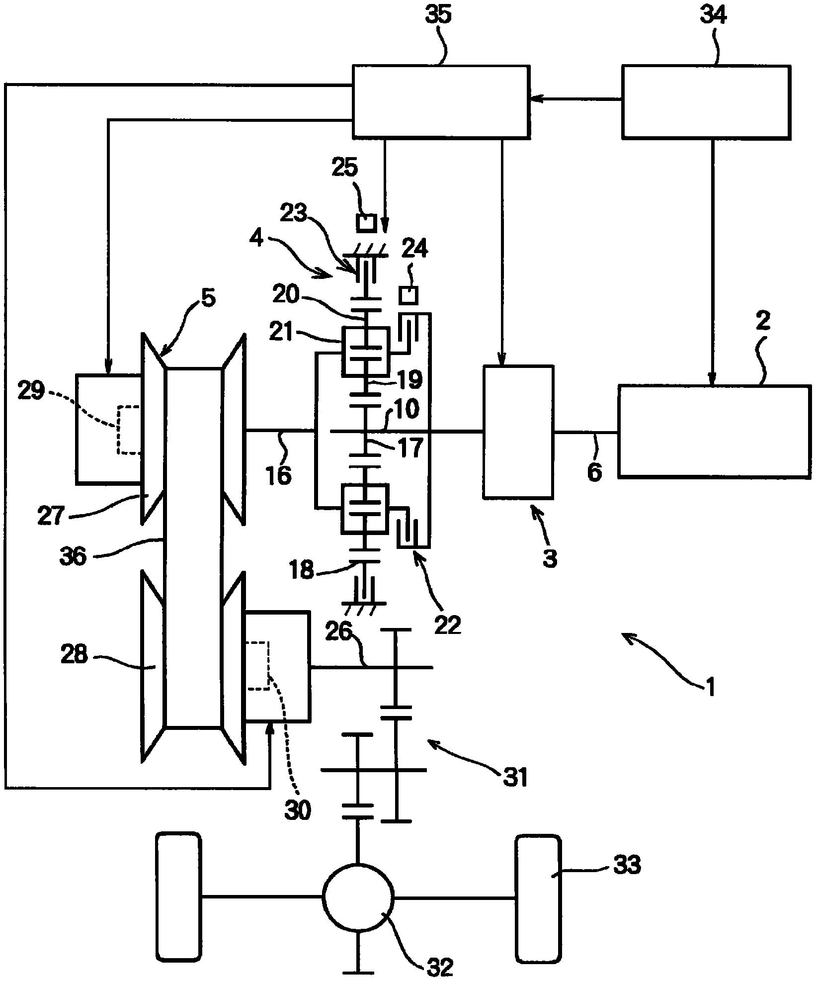
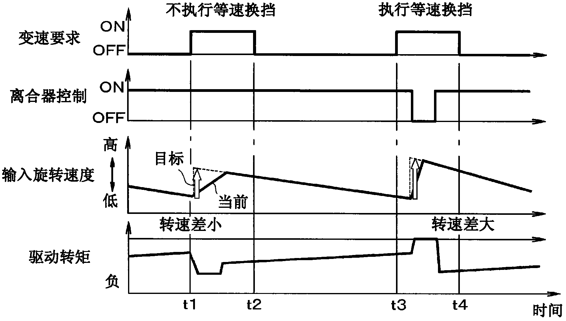
[0035] In the present invention, the continuously variable transmission has a structure that can change the gear ratio continuously (steplessly) and change the gear ratio stepwise (stepwise). The continuously variable transmission of the present invention includes: a belt type continuously variable transmission, a ring type continuously variable transmission and a continuously variable transmission using a planetary gear mechanism. In addition, in the present invention, the clutch is configured such that the transmission torque or torque capacity can be controlled, and power can be transmitted and cut off by the clutch. The aforementioned clutch includes a clutch that transmits power by frictional force, electromagnetic force, or meshing force. The shift shock in the present invention refers to a sudden change in the driving torque of the vehicle due to the shift of the continuously variable transmission. Here, "sharp" refers to the degree to which the driver can feel. In pa...


PUM


Abstract

Provided is a driving force control device capable of suppressing shifting shocks when a speed ratio is stepwise changed by a continuously variable transmission. The driving force control device has the continuously variable transmission connected in a power transmittable manner to the output shaft of an internal combustion engine through a clutch so that the device can change the speed ratio of the continuously variable transmission stepwise. The driving force control device comprises a shift deciding means (Step S1) for deciding whether or not the torque capacity of the clutch is relatively high and whether or not the speed ratio of the continuously variable transmission is stepwise changed while the vehicle is running, and a first shifting means (Step S3) for lowering the torque capacity of the clutch, when the speed ratio of the continuously variable transmission is stepwise changed, before the speed ratio is changed by the continuously variable transmission, synchronizing the rotating speed of the internal combustion engine, while the speed ratio is being changed by the continuously variable transmission, with the input rotating speed after the speed ratio is changed by the continuously variable transmission, and raising the torque capacity of the clutch after the speed ratio is changed by the continuously variable transmission.

Description

[0001] technology area [0002] The present invention relates to a driving force control device in which a continuously variable transmission is connected to an output shaft of an internal combustion engine in a power-transmittable manner. Background technique [0003] Conventionally, a driving force control device in which a continuously variable transmission is connected to an output shaft of an internal combustion engine is known. Since the gear ratio which is the ratio of the input rotational speed to the output rotational speed can be controlled steplessly in this continuously variable transmission, the operating state of the internal combustion engine can be controlled in a fuel-efficient manner. Accordingly, JP-A-2006-125602 describes an example of a control device in which a continuously variable transmission is connected to an output shaft of an internal combustion engine so that power transmission is possible. In this Japanese Patent Laid-Open No. 2006-125602, a bel...

Claims


Application Information

Patent Timeline
Patent Type & Authority Applications(China)
IPC IPC(8): B60W10/02B60W10/06B60W10/10B60W30/18
CPCB60W10/02B60W10/06B60W10/107B60W30/19B60W2510/0275B60W2710/0644F16H37/022F16H61/0437F16H61/662F16H61/66259F16H61/66272F16H2061/661F16H2061/6615F16H2061/6618F16H2306/42F16H2342/044
Inventor 本多义行
Owner TOYOTA JIDOSHA KK
Why Eureka
Try Eureka