Method and apparatus to control off-going clutch torque during torque phase

A clutch and torque technology, applied in the field of control systems

Inactive Publication Date: 2013-06-19
GM GLOBAL TECH OPERATIONS LLC
View PDF0 Cites 0 Cited by
  • Summary
  • Abstract
  • Description
  • Claims
  • Application Information

AI Technical Summary

Problems solved by technology

Because unlocking necessarily involves a rapid drop in clamping force, engine and motor torques that generate excessive reactive torque on the clutch during an unlocking event pose a drivability risk of possible slip

Method used


Image

  • Method and apparatus to control off-going clutch torque during torque phase
  • Method and apparatus to control off-going clutch torque during torque phase
  • Method and apparatus to control off-going clutch torque during torque phase

Examples


Embodiment Construction

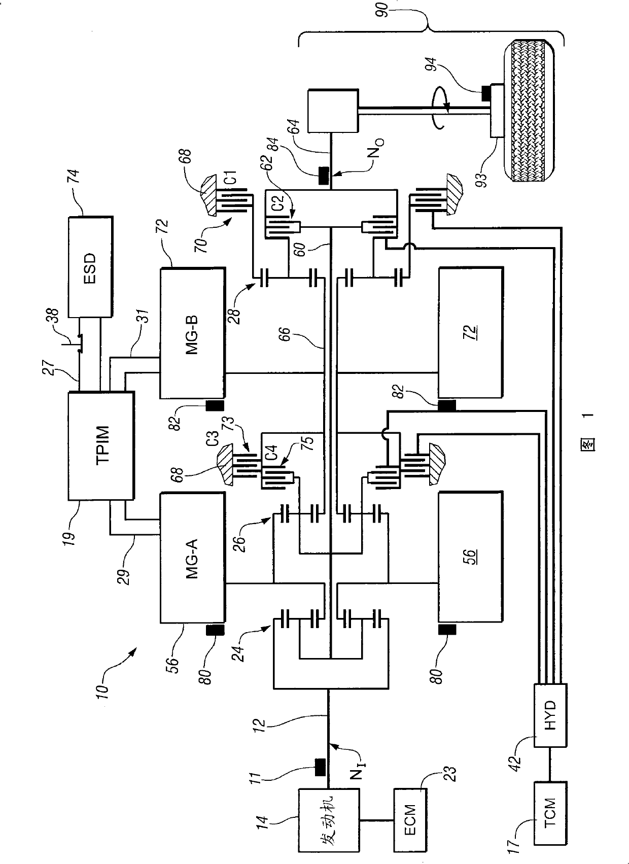
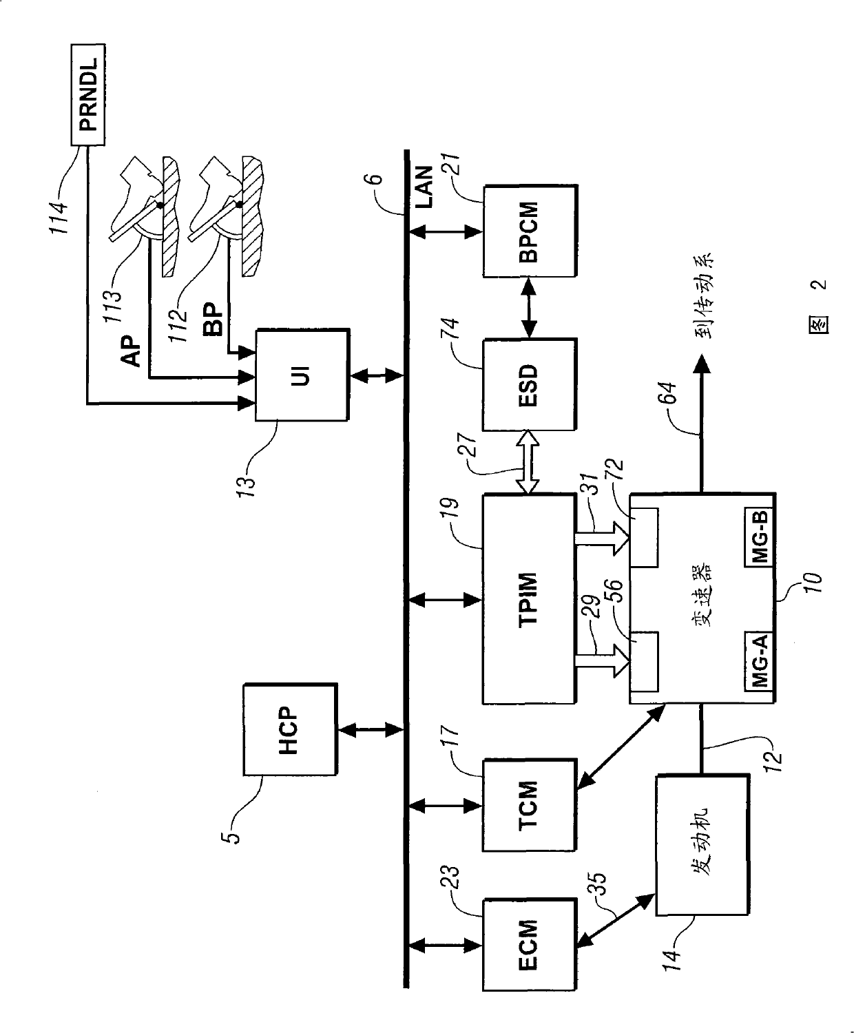
[0020] Reference is now made to the drawings, in which the drawings are for purposes of illustrating certain exemplary embodiments only and are not intended to be limiting thereof. figure 1 and 2 An exemplary electromechanical hybrid powertrain is depicted. figure 1 Depicted is an exemplary electromechanical hybrid powertrain according to the present disclosure comprising a two-mode compound split electromechanical hybrid transmission 10 operatively connected to an engine 14 and a first electric machine ('MG-A') 56 and a second motor ('MG-B') 72 . The engine 14 and the first electric machine 56 and the second electric machine 72 each generate power transmittable to the transmission 10 . The power generated by the engine 14 and the first and second electric machines 56 and 72 and transmitted to the transmission 10 is based on the power, respectively referred to herein as T I , T A and T B The input torque and are referred to in this paper as N I , N A and N B explained ...


PUM


Abstract

A method for controlling an electro-mechanical transmission (10) through an unlocking state of a clutch (70,62,73,75), the transmission mechanically-operatively coupled to an internal combustion engine (14) and an electric machine (56,72) adapted to selectively transmit mechanical power to an output member (64) includes decreasing a reactive torque acting upon the clutch (70,62,73,75), including overriding torque commands to the engine (14) and to the electric machine (56,72), and simultaneously decreasing a clutch torque capacity, including, during a lead period selected according to an engine command reaction time, commanding an intermediate clutch torque command maintaining sufficient clutch torque capacity to exceed an initial reactive torque calculated at an initiation of the unlocking state, and following the lead period, decreasing through a ramp down the clutch torque capacity, maintaining sufficient clutch torque capacity to exceed the decreasing reactive torque.

Description

[0001] Cross References to Related Applications [0002] This application claims priority to US Provisional Application 60 / 982,463, filed October 25, 2007, which is hereby incorporated by reference. technical field [0003] The invention relates to a control system for an electromechanical transmission. Background technique [0004] The statements in this section merely provide background information related to the present disclosure and may not constitute prior art. [0005] Known driveline architectures include torque-generative devices, including an internal combustion engine and an electric machine, that transmit torque to an output member through a transmission. An exemplary powertrain includes a dual-mode compound split electromechanical transmission and an output member that utilizes an input member to receive motive torque from a prime mover power source, preferably an internal combustion engine. The output member is operatively connected to the vehicle driveline f...

Claims


Application Information

Patent Timeline
Patent Type & Authority Patents(China)
IPC IPC(8): F16H61/00F16H61/32F16H59/14F16H3/72
CPCY02T10/6286B60W2540/10B60W2540/12B60W10/06B60W2510/104B60W10/02B60K6/547F16H2037/106B60K6/445B60L2240/421F16H2037/104B60W10/08Y02T10/6221B60L2240/441Y02T10/6239F16H2037/102B60W2710/025F16H2037/0866F16H3/728B60L2240/486B60K6/365B60W20/00B60K6/26B60K1/02B60W2510/0241Y02T10/642B60W2510/081B60W2510/0638Y02T10/62Y02T10/64B60W2050/0042B60W20/40
Inventor A·H·希普L·A·卡明斯基J·-J·F·萨
Owner GM GLOBAL TECH OPERATIONS LLC
Why Eureka
Try Eureka