
A demagnetization starting device for a superconducting DC induction heating motor

A technology of DC induction and starting device, which is applied in the direction of induction heating device, induction heating, electric heating device, etc. It can solve the problems of motor damage, reduce the service life of the motor, and cumbersome operation, so as to improve the service life, ensure normal start, and simplify operation. The effect of the process

Active Publication Date: 2021-04-02
JIANGXI LIANCHUANG OPTOELECTRONIC SCIENCE AND TECHNOLOGY CO LTD
View PDF6 Cites 0 Cited by
  • Summary
  • Abstract
  • Description
  • Claims
  • Application Information

AI Technical Summary

Problems solved by technology

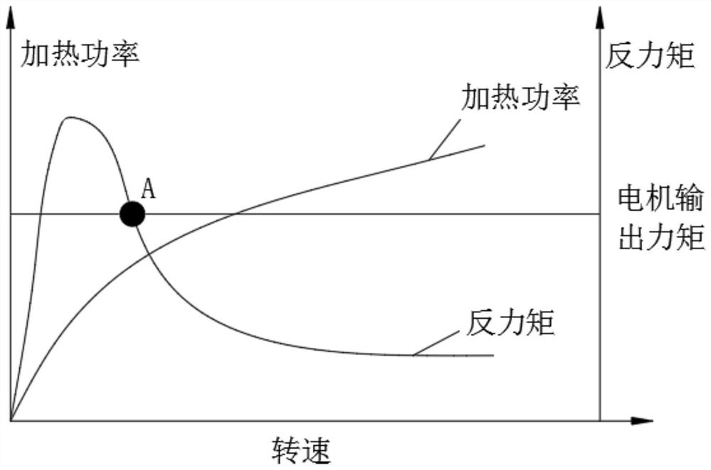
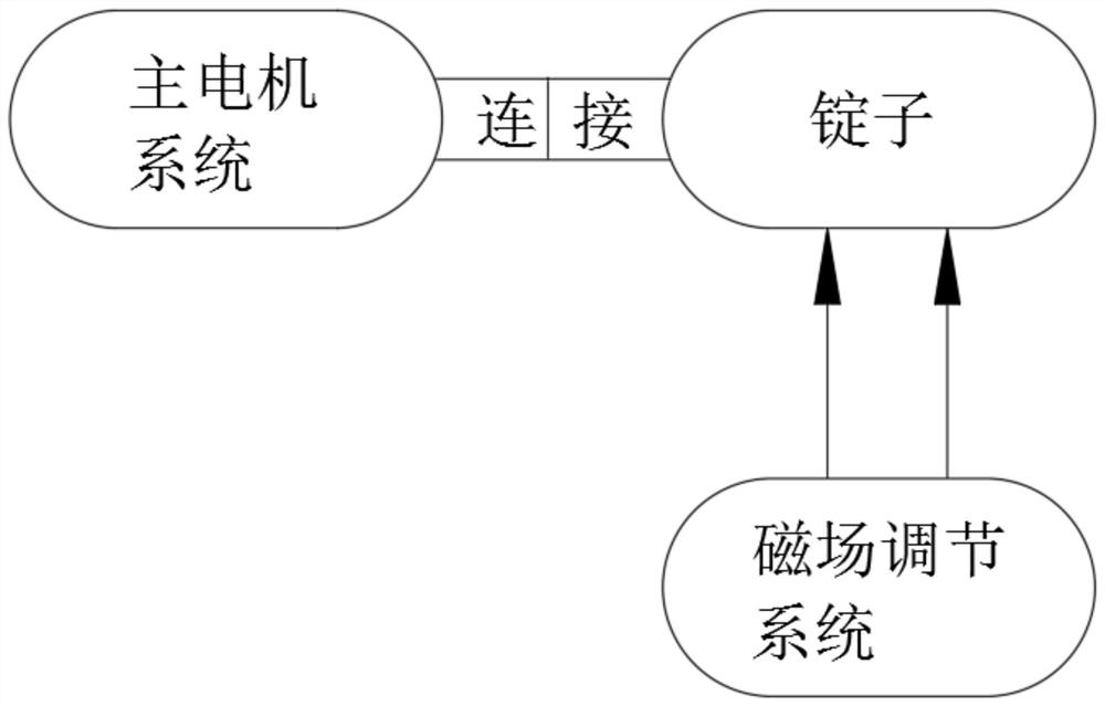
[0004] see image 3 and Figure 4 , the existing starting device generally uses an auxiliary motor to increase the rotational torque to assist the spindle to reach the target speed or control the size of the magnetic field to gradually increase the magnetic field to complete the start after reaching a certain speed. These two methods require additional control devices or even drive devices. , the operation is more cumbersome, while increasing the complexity of the device and reducing the reliability of the system
[0005] Furthermore, since the starting device is relative to the independent heating system, when the spindle speed decreases due to an accident, the counter torque generated by the spindle will be greater than the output motor of the motor. On the one hand, the spindle cannot maintain the target speed and needs to be restarted. On the one hand, the spindle is in an overload state, which will cause great damage to the motor and reduce the service life of the motor

Method used


Image

  • A demagnetization starting device for a superconducting DC induction heating motor
  • A demagnetization starting device for a superconducting DC induction heating motor
  • A demagnetization starting device for a superconducting DC induction heating motor

Examples


Embodiment Construction

[0023] The following will clearly and completely describe the technical solutions in the embodiments of the present invention with reference to the accompanying drawings in the embodiments of the present invention. Obviously, the described embodiments are only some, not all, embodiments of the present invention. Based on the embodiments of the present invention, all other embodiments obtained by persons of ordinary skill in the art without making creative efforts belong to the protection scope of the present invention.

[0024] see Figure 1-7 , a demagnetization starting device for a superconducting DC induction heating motor, comprising a flywheel 1, the flywheel 1 is an insulating material, and the quality of the flywheel 1 is relatively large relative to the spindle, so as to ensure the stable rotation of the spindle, and the inner and outer edges of the flywheel 1 are respectively provided with The outer conductive ring 2 and the inner conductive ring 3, the outer conduct...


PUM


Abstract

The invention relates to the technical field of heating equipment and discloses a demagnetization starting device of a superconducting DC induction heating motor. The demagnetization starting device comprises a flywheel, wherein the inner and outer edges of the flywheel are provided with an outer conductive ring and an inner conductive ring respectively; and the outer conductive ring and the innerconductive ring are connected to a superconducting coil circuit through an outer brush and an inner brush, respectively. In the demagnetization starting device of the superconducting DC induction heating motor, the magnetic field is automatically adjusted as the rotational speed increases, thereby ensuring that the output torque of the motor is always greater than the counter torque generated bya spindle, ensuring the normal starting of a heating device, and greatly simplifying an operation procedure. On the one hand, the structures used in the demagnetization starting device are all simplewear-resistant components which are reliable to use. Further, since the demagnetization starting device automatically controls the magnitude of the magnetic field according to the rotational speed, the magnetic field also decreases when the spindle speed is lowered due to an accident such that the output torque of the motor is always greater than the counter torque and the motor always operates under a rated condition.

Description

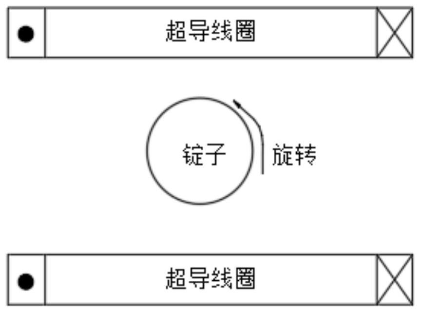
technical field [0001] The invention relates to the technical field of heating equipment, in particular to a demagnetization starting device for a superconducting DC induction heating motor. Background technique [0002] The DC induction heating method is suitable for heating non-magnetic materials with low resistivity such as aluminum ingots or copper ingots, and its heating efficiency can reach more than 90%. The heating principle is as follows: figure 1 As shown, the direct current passes through the magnet composed of superconducting coils to form a strong direct current magnetic field, and the spindle rotates to cut the magnetic field lines, thereby generating eddy currents inside the spindle and further generating Joule heat to heat the spindle. [0003] During operation, the eddy current generated in the spindle will hinder the counter torque of the spindle rotation, and convert the mechanical energy of the spindle into heat energy through electromagnetic induction. T...

Claims


Application Information

Patent Timeline
Patent Type & Authority Patents(China)
IPC IPC(8): H02P1/16H05B6/10H05B6/44H05B6/36
CPCH02P1/16H05B6/101H05B6/365H05B6/44
Inventor 蒋国忠黄建民李芳昕吴启峰饶志文倪国华周呈劼谭云海杨平
Owner JIANGXI LIANCHUANG OPTOELECTRONIC SCIENCE AND TECHNOLOGY CO LTD
Learn More