Permanent-magnet rotor deflection-type three-degree-of-freedom motion motor

A technology of permanent magnet rotor and degree of freedom, which is applied in the direction of electrical components, magnetic attraction or thrust holding device, etc., which can solve the problems of poor torque output capability and large wear of three-degree-of-freedom motion motors, and achieve torque output capability Strong, improved dynamic response and positioning accuracy, reduced moment of inertia

Active Publication Date: 2012-05-30
HEBEI UNIVERSITY OF SCIENCE AND TECHNOLOGY
View PDF4 Cites 14 Cited by
  • Summary
  • Abstract
  • Description
  • Claims
  • Application Information

AI Technical Summary

Problems solved by technology

[0007] The purpose of the present invention is to provide a permanent magnet rotor deflection type three-degree-of-freedom motion motor, the purpose is to solve the existing three-degree-of-freedom motion motor with large wear and torque output capacity Its structure is relatively simple, easy to control, high mechanical integration, small wear, strong torque output capability, good static and dynamic performance, and easy to achieve suspension control

Method used


Image

  • Permanent-magnet rotor deflection-type three-degree-of-freedom motion motor
  • Permanent-magnet rotor deflection-type three-degree-of-freedom motion motor
  • Permanent-magnet rotor deflection-type three-degree-of-freedom motion motor

Examples


Embodiment Construction

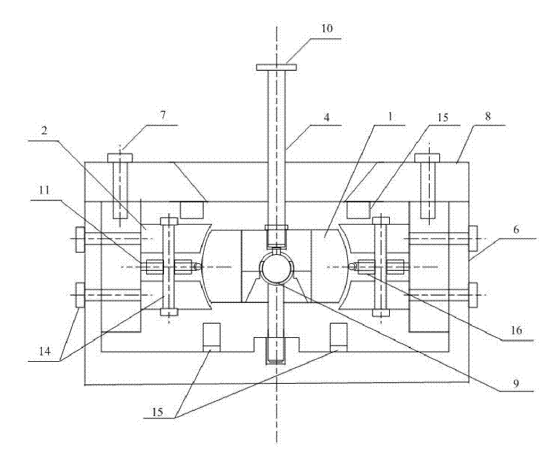
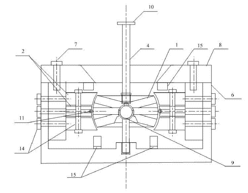
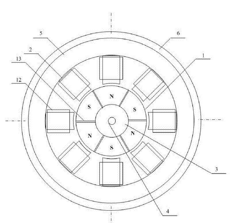
[0040] see figure 1 , 2 , 3 and 4, the drum-shaped and butterfly-shaped rotors are composed of magnetic poles 1 made of permanent magnetic materials and magnetic spacers 13 between the magnetic poles. The motor body has stators, coils and rotors. The base and stator shell 6 are fixed as one. The shell The end cover 8 is in the shape of a trumpet with an opening on the side of the output shaft, and fixing screw holes are distributed on the inner surface of the casing to fix the stator core 2, the bearing 9 and the magnetic sensor group 15 respectively.

[0041] On the rotor, permanent magnet slots are distributed according to the principle of equal division. The permanent magnets arranged radially along the output shaft in the adjacent permanent magnet slots are distributed alternately with N poles and S poles. The drum-shaped rotor has a single-layer structure, and the butterfly rotor The cross structure constitutes a three-layer structure; the bottom adjustable screw ball be...


PUM


Abstract

The invention provides a permanent-magnet rotor deflection-type three-degree-of-freedom motion motor, which relates to the technical field of permanent-magnet rotor motors. The motion motor is characterized in that magnetism isolating sheets and permanent magnets consisted of non-magnetic-conduction materials are distributed on the outer side of the inner core of the rotor. N-poles and S-poles are distributed in a staggered way and the outlines of the permanent magnets are spherical. At least two layers of magnetic pole iron cores are provided on the rotor of the periphery. Stator magnetic pole loops are provided on the magnetic pole iron cores. An output shaft is rigidly connected with center of the stator, the center of an outer housing overlaps with center of the rotor and the rotor is supported by a circular ball bearing fixed on the stator. The stator is provided with a transducer for detecting the position and the speed of the rotor so as to realize closed-loop control of the motor. The motion motor of the invention solves the problems of the three-degree-of-freedom motion motor in the prior art, including heavy abrasion, poor torque output capacity and the like. The motion motor of the invention is relatively simple in structure, easy to control, high in mechanical integration level, small in abrasion, strong in torque output capacity, and excellent in static and dynamic performance. In addition, the motion motor can realize suspension control.

Description

[0001] technical field [0002] The invention relates to the technical field of permanent magnet rotor motors. Background technique [0003] The traditional method of realizing multi-degree-of-freedom motion is to use multiple single-degree-of-freedom motors with mechanical transmission devices, which easily leads to a decrease in accuracy and efficiency, and is often bulky and expensive. Using multi-degree-of-freedom motors, especially three-degree-of-freedom motors to achieve complex movements is an ideal solution at present. This type of motor is widely used in robot joints, omni-directional drive hubs, panoramic camera platforms, space measurement, multi-directional transmission structures, etc. field. [0004] The multi-degree-of-freedom motor with permanent magnets can greatly increase the magnetic energy product of the motor, effectively improve the operating efficiency of the motor, reduce the volume of the motor, and improve the controllability of the motor. The d...

Claims


Application Information

Patent Timeline
Patent Type & Authority Applications(China)
IPC IPC(8): H02N15/00
Inventor 李争
Owner HEBEI UNIVERSITY OF SCIENCE AND TECHNOLOGY
Why Eureka
Try Eureka