Scanning mechanism applied to aerial camera

A scanning mechanism and aerial camera technology, applied in the field of aero-optical remote sensors, can solve the problems of inability to achieve fast, flexible and accurate control, increased inertia of the scanning mechanism, large volume and mass, etc., and achieves fast, flexible and accurate control, simple structure, and volume. small effect

Active Publication Date: 2013-12-25
BEIJING RES INST OF SPATIAL MECHANICAL & ELECTRICAL TECH
View PDF4 Cites 15 Cited by
  • Summary
  • Abstract
  • Description
  • Claims
  • Application Information

AI Technical Summary

Problems solved by technology

[0003] At present, the traditional scanning mechanism mostly uses a deceleration device, which makes the volume and mass of the whole mechanism larger, resulting in an increase in the inertia of the scanning mechanism. When the scanning mechanism is operated and controlled, there will be a large lag and overshoot in time. Fast, flexible and accurate control cannot be achieved

Method used


Image

  • Scanning mechanism applied to aerial camera
  • Scanning mechanism applied to aerial camera
  • Scanning mechanism applied to aerial camera

Examples


Embodiment

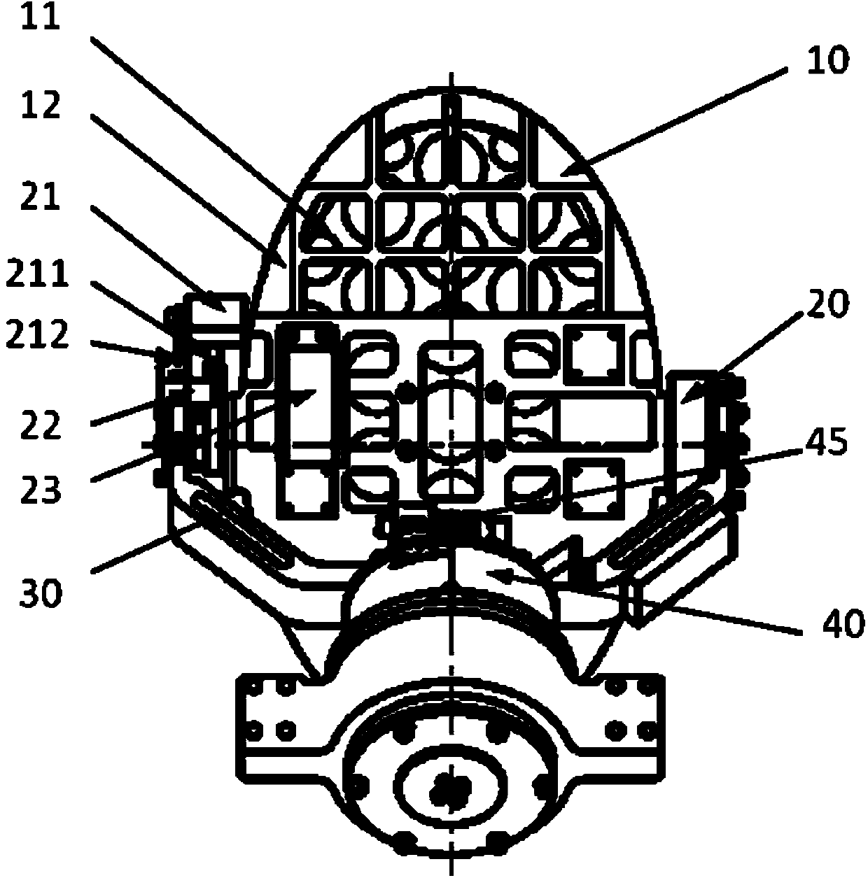
[0031] A scanning mechanism applied to an aerial camera, the scanning mechanism is fixedly connected with the camera main body through a fixing seat;

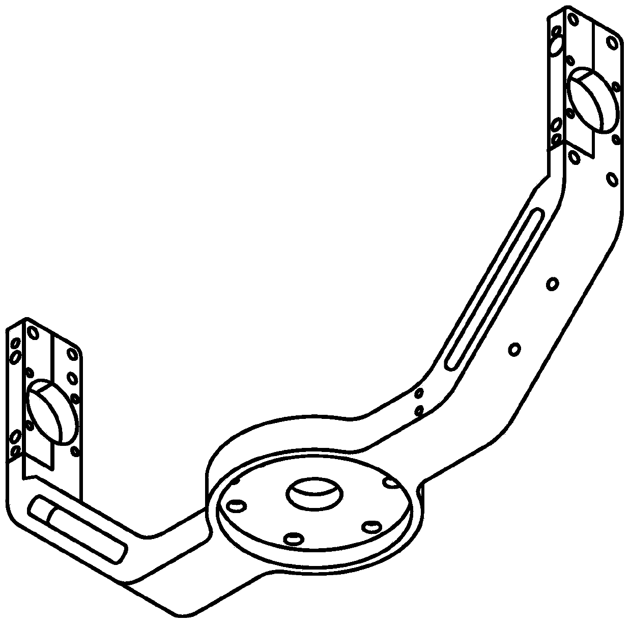
[0032] Such as figure 1 As shown, the scanning mechanism includes a scanning mirror assembly 10, a pitch shaft assembly 20, a U-shaped ring 30 and a roll shaft assembly 40; the scanning mirror assembly 10 is fixedly connected to the pitch shaft assembly 20 through a pitch shaft 28; the pitch shaft The component 20 is flexibly connected to both ends of the U-shaped ring 30; the rolling shaft assembly 40 is fixedly connected to the middle of the U-shaped ring 30; the structural diagram of the U-shaped ring 30 is as follows image 3 shown;

[0033] The scanning mirror assembly 10 includes a scanning mirror 11 and a mirror frame 12, and the scanning mirror 11 is fixed in the mirror frame 12 with stress-free glue;

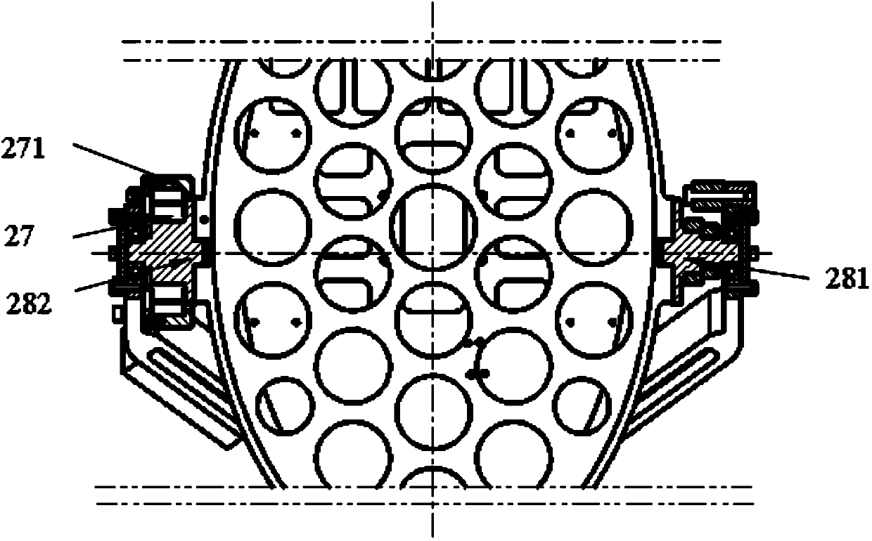
[0034] Such as figure 1 and figure 2 As shown, the pitch shaft assembly 20 includes a pitch shaft 28, a voice coi...


PUM


Abstract

The invention relates to a scanning mechanism applied to an aerial camera, in particular to a scanning mechanism which performs automatic, fast and accurate image motion compensation on an aerial camera, and belongs to the technical field of aerial optical remote sensors. According to the scanning mechanism, through adopting a pitching limiting component and a rolling limiting component, a motor is prevented from rotating under the condition of loss of control, and further a connection wire is prevented from winding or being snapped; a spring is arranged in the rolling limiting component, so that the impact to a scanning reflection mirror from the motor under the condition of the loss of control is reduced, and further the disturbance to the camera is reduced; the pitching limiting component is coated with polytetrafluoroethylene, so that the impact is reduced.

Description

technical field [0001] The invention relates to a scanning mechanism applied to aerial cameras, in particular to a scanning mechanism for automatically performing fast and accurate image motion compensation on aerial cameras, belonging to the technical field of aerial optical remote sensors. Background technique [0002] With the rapid development of aviation technology, the requirements for the imaging quality of optical remote sensors are getting higher and higher. The imaging quality of aerial cameras is affected by many factors, including the hardware of the camera itself, the airborne platform, and environmental conditions. The image motion caused by the motion of the airborne platform is an important factor affecting the imaging quality. Therefore, image motion compensation must be performed to obtain high-definition and high-resolution aerial images. In addition, infrared cameras are limited by the level of detector development, with few pixels and large pixel sizes....

Claims


Application Information

Patent Timeline
Patent Type & Authority Applications(China)
IPC IPC(8): G01C11/00G02B26/10
Inventor 贾晓梅王哲林招荣姚毅刚安超董欣
Owner BEIJING RES INST OF SPATIAL MECHANICAL & ELECTRICAL TECH
Why Eureka
Try Eureka