
An automatic anti-wear and torque-reducing tool for coiled tubing

A technology for coiled tubing and tools, applied in the field of automatic anti-wear and torsion-reducing tools, can solve the problems of reducing drilling efficiency, twisting and breaking of coiled tubing, chipping drilling tools, etc., achieving good practicability, reducing back torque, and improving work efficiency Effect

Active Publication Date: 2021-04-27
YANGTZE UNIVERSITY
View PDF4 Cites 0 Cited by
  • Summary
  • Abstract
  • Description
  • Claims
  • Application Information

AI Technical Summary

Problems solved by technology

[0002] In the process of exploration and development of oil and gas wells, coiled tubing is generally used for drilling operations. This drilling method is to transmit ground power to drilling tools through coiled tubing, thereby breaking rocks through drilling tools; when coiled tubing is used for drilling operations, There must be contact between the drilling tool and the rock and there is frictional resistance. The existence of frictional resistance will cause the drilling tool to generate counter torque. When the frictional resistance increases with the increase of the ground force, the counter torque generated by the drilling tool will also Then it will become larger, and the excessive counter torque will easily cause the drill bit to break teeth and cause damage to the drilling tool; at the same time, when the drill tool generates excessive counter torque and transmits it to the coiled tubing, the coiled tubing will easily be twisted off, resulting in economical damage. Loss, but also reduce drilling efficiency; therefore, it is very important to develop an anti-wear and torque-reducing tool

Method used


Image

  • An automatic anti-wear and torque-reducing tool for coiled tubing
  • An automatic anti-wear and torque-reducing tool for coiled tubing
  • An automatic anti-wear and torque-reducing tool for coiled tubing

Examples


Embodiment Construction

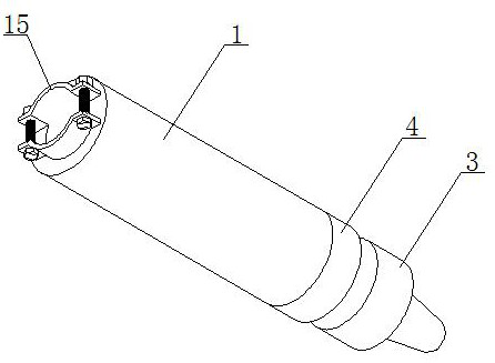
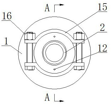
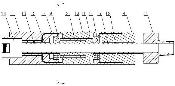
[0025] The automatic anti-wear and torque-reducing tool for coiled tubing operation consists of a housing 1, a mandrel 2, a lower joint 3 and a mounting seat 4. The housing 1 is cylindrical in shape, and one end of the housing 1 is provided with a stepped hole. , the upper bearing 5 is fixedly installed on the stepped hole, the other end of the housing 1 is provided with a limiting shoulder, and the lower bearing 6 is fixedly installed on the limiting shoulder.

[0026] Inside the housing 1, the mandrel 2 is movably installed through the upper bearing 5 and the lower bearing 6, and the upper bearing 5 and the lower bearing 6 center the mandrel 2 in the housing 1; the mandrel 2 is in the shape of a reducing cylinder Sealing ring A9 is set between the mandrel 2 above the upper bearing and the housing 1, and the mandrel 2 forms a sealed state through the annular layer between the sealing ring A9 and the housing 1, so as to prevent the mandrel 2 from being connected to the housing ...


PUM


Abstract

The invention relates to an automatic anti-wear and torque-reducing tool for coiled tubing operations, which belongs to the technical field of downhole tools. It consists of a shell, a mandrel, a lower joint and a mounting seat. The interior of the shell is equipped with a mandrel through the upper bearing and the lower bearing. The mandrel below the lower bearing is fitted with a mounting seat. Threaded connection, one end of the mandrel extends to the outer end of the mounting seat, and a lower joint is threadedly installed on the end of the mandrel extending to the outer end of the mounting seat. The anti-wear and torque-reducing tool uses the principle of electromagnetism in its work to make the coiled tube and the drilling tool realize the state of energization and attraction, and the coiled tube can transmit torque to the drilling tool. When the counter torque of the drilling tool is greater than the coiled tube and the When the electromagnetic connection force between the drilling tools is used, the coiled tubing and the drilling tool are disconnected, which effectively protects the coiled tubing and the drilling tool from being damaged, reduces the risk of economic loss, and effectively improves work efficiency.

Description

technical field [0001] The invention relates to an automatic anti-wear and torque-reducing tool for coiled tubing operations, which belongs to the technical field of downhole tools. Background technique [0002] In the process of exploration and development of oil and gas wells, coiled tubing is generally used for drilling operations. This drilling method is to transmit ground power to drilling tools through coiled tubing, thereby breaking rocks through drilling tools; when coiled tubing is used for drilling operations, There must be contact between the drilling tool and the rock and there is frictional resistance. The existence of frictional resistance will cause the drilling tool to generate counter torque. When the frictional resistance increases with the increase of the ground force, the counter torque generated by the drilling tool will also Then it will become larger, and the excessive counter torque will easily cause the drill bit to break teeth and cause damage to th...

Claims


Application Information

Patent Timeline
Patent Type & Authority Patents(China)
IPC IPC(8): E21B17/02E21B17/20
CPCE21B17/028E21B17/20
Inventor 刘少胡汪伟俊江山钟虹
Owner YANGTZE UNIVERSITY
Learn More