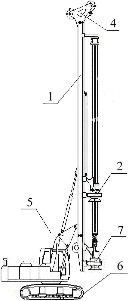
Rotary drilling rig

A technology for rotary drilling rigs and connecting brackets, which is applied to rotary drilling rigs, rotary drilling, earthwork drilling and mining, etc. It can solve the problem of unchangeable distances, achieve convenient operation, strong practicability, and increase the stability of the whole machine Effect

Active Publication Date: 2015-04-29
SHANGHAI ZOOMLION HEAVY IND PILING MACHINERYCO +1
View PDF3 Cites 0 Cited by
  • Summary
  • Abstract
  • Description
  • Claims
  • Application Information

AI Technical Summary

Problems solved by technology

And as figure 2 In the prior art shown, the power head 2 and the mast 1 are fixedly connected by two connecting pins, that is to say, the distance cannot be changed

Method used


Image

  • Rotary drilling rig
  • Rotary drilling rig
  • Rotary drilling rig

Examples


Embodiment Construction

[0027] Specific embodiments of the present invention will be described in detail below in conjunction with the accompanying drawings. It should be understood that the specific embodiments described here are only used to illustrate and explain the present invention, and are not intended to limit the present invention.

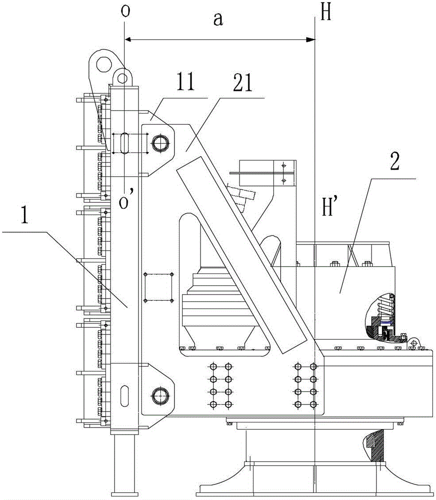
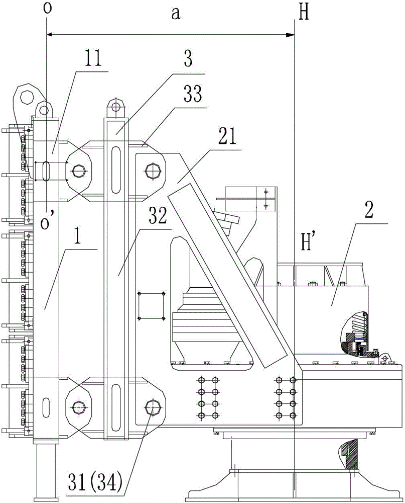
[0028] In the present invention, unless stated to the contrary, the used orientation words such as "up, down, and sideways" are generally for the directions shown in the drawings or for vertical, perpendicular or gravity directions. Words are used to describe the mutual positional relationship of each component. The term "center distance" in this specification specifically refers to the minimum distance or level between the central axis HH' of the power head and the central axis OO' of the mast when the mast 1 and the power head 2 are in the vertical working state shown in the drawings. distance.

[0029] Such as image 3 As shown, the present invention provi...


PUM


Abstract

The invention discloses a rotary drilling rig, which includes a mast (1) and a power head (2), wherein a mounting frame (21) is arranged on the power head (2); a sliding framework (11) is arranged on the mast (1); the rotary drilling rig further includes connecting brackets (3); the sliding framework (11) is connected with the mounting frame (21) through the connecting brackets (3) arranged therebetween; and one or more connecting brackets (3) can be arranged as required. The rotary drilling rig provided by the invention has a simple structure, is convenient to operate, improves the complete machine stability during the operation, meanwhile reduces the reactive torque exerted on the guiding rail of the mast, and is strong in practicability, as the required center distance (a) can be adjusted through mounting or dismounting the connecting brackets (3) as per the required center distance (a) between the mast (1) and the power head (2).

Description

technical field [0001] The invention relates to a rotary drilling rig, in particular to a rotary drilling rig with adjustable center distance between a mast and a power head. Background technique [0002] attached figure 1 It is a structural schematic diagram of a rotary drilling rig according to the prior art. Such as figure 1 As shown, the rotary drilling rig has a foldable mast 1 that can rise and fall by itself. The mast 1 can be stacked on the crawler vehicle 6 of the rotary drilling rig in a non-working state for transportation, and in the working state, it is driven by a thrust cylinder such as a hydraulic cylinder. Push and stand and the position can be adjusted by luffing mechanism 5. An anchor frame 4 is installed on the top of the mast 1, and the rotary drilling rig operates the wire rope through its hoisting system. The wire rope is set to pass through the pulley on the anchor frame 4 and pull the drill pipe in the vertical direction. The drill rod thereby ma...

Claims


Application Information

Patent Timeline
Patent Type & Authority Patents(China)
IPC IPC(8): E21B3/02E21B15/00
Inventor 孙涛常延沛孔祥玉郑浩茅晓峰梁海龙
Owner SHANGHAI ZOOMLION HEAVY IND PILING MACHINERYCO
Why Eureka
Try Eureka