
powerplant

A technology for power plant and generating device, applied in power plant, electric power plant, transmission and other directions, can solve the problems of internal combustion engine consumption, large drag loss, large-scale device and reduced mountability, etc., to reduce losses and improve mountability. , the effect of miniaturization

Active Publication Date: 2016-11-16
HONDA MOTOR CO LTD
View PDF2 Cites 0 Cited by
  • Summary
  • Abstract
  • Description
  • Claims
  • Application Information

AI Technical Summary

Problems solved by technology

Therefore, when a wet friction clutch is used as the clutch for speed-up and speed-down, a large drag loss will occur due to the shear resistance due to the viscosity of the lubricating oil.
[0011] Furthermore, when a hydraulic pump using an internal combustion engine as a power source is used to supply hydraulic pressure to hydraulic speed-up and deceleration clutches, the distribution control of the torque to the left and right output shafts will not be controlled during the operation of the internal combustion engine. , both drive the hydraulic pump all the time, so that the torque of the internal combustion engine is correspondingly wasted for nothing
In addition, since a spool, a solenoid, a filter, and the like are required for driving the clutches for increasing speed and speed reducing, the size of the device increases and the mountability decreases accordingly.

Method used


Image

  • powerplant
  • powerplant
  • powerplant

Examples


Embodiment Construction

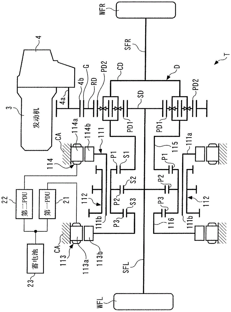
[0074] Hereinafter, preferred embodiments of the present invention will be described in detail with reference to the drawings. figure 1 The illustrated internal combustion engine (hereinafter referred to as "engine") 3 is mounted on a FF (Front Engine-Front Drive) type four-wheeled vehicle (not shown). The power transmission device T according to the first embodiment of the present invention is connected to the engine 3 via the transmission 4, and transmits the torque of the engine 3 (hereinafter referred to as "engine torque") to the left front wheel WFL and the right front wheel WFR of the vehicle. .

[0075] The power transmission device T includes a differential device D, a carrier member 111 , a triple pinion 112 , a first electric motor 113 , and a second electric motor 114 . The aforementioned differential device D, the carrier member 111 , the first electric motor 113 , and the second electric motor 114 are arranged coaxially with each other. The differential device...


PUM


Abstract

The present invention provides a power plant capable of suppressing loss and realizing downsizing and improving mountability of the device. In the power unit (T), the rotation speeds of the third to first sun gears (S3-S1) and the carrier member (111) are in a collinear relationship with each other, and are arranged sequentially in a collinear diagram showing the relationship between the rotation speeds. Moreover, the third sun gear (S3) and the planetary gear carrier member (111) are respectively connected with the first and second torque generators (113, 114) capable of generating positive torque and negative torque, and the second and second One sun gear (S2, S1) is connected to one and the other of the two rotating shafts, respectively.

Description

technical field [0001] The present invention relates to a power unit that drives two rotating shafts configured to be differentially rotatable relative to each other to move a moving device. Background technique [0002] Conventionally, as such a power plant, for example, a configuration disclosed in Patent Document 1 is known. This conventional power unit is applied to a four-wheeled vehicle and includes an internal combustion engine as a power source, a differential device that distributes the torque of the internal combustion engine to left and right output shafts, a rotatable planetary carrier member, and is supported by the planetary carrier member for rotation. Free triple pinion, hydraulic clutch for speed-up and speed-down. The left and right output shafts are respectively connected to the left and right drive wheels. Furthermore, the triple pinion gear is composed of a first pinion gear, a second pinion gear, and a third pinion gear having mutually different pitch...

Claims


Application Information

Patent Timeline
Patent Type & Authority Patents(China)
IPC IPC(8): F16H48/06B60K1/02B60K6/08B60K6/365F16H1/28F16H48/36
CPCB60K6/52F16H48/06F16H48/36B60K1/02F16H2048/364Y10S903/902Y02T10/62B60K6/547
Inventor 本多健司
Owner HONDA MOTOR CO LTD
Learn More