
Vehicle behavior controller

A technology of control devices and braking devices, applied in the direction of brakes, etc., can solve the problems of stable control delay and time delay, and achieve the effect of improving behavior stability

Active Publication Date: 2014-05-14
TOYOTA JIDOSHA KK
View PDF1 Cites 0 Cited by
  • Summary
  • Abstract
  • Description
  • Claims
  • Application Information

AI Technical Summary

Problems solved by technology

However, when the braking force is generated on the wheels, it is necessary to activate the hydraulic pump or operate the valve as described above, so there is likely to be a time delay from when the braking force generation command is issued until the braking force is actually generated.
[0004] On the other hand, when the vehicle behavior control device generates braking force on the wheels in order to stabilize the behavior, it is necessary to generate the braking force quickly so that the unstable behavior such as the spin mode or the vehicle that is not accompanied by the driving operation Behavior is stabilized, but if the braking force is delayed, so is the control used to achieve stabilization

Method used


Image

  • Vehicle behavior controller
  • Vehicle behavior controller
  • Vehicle behavior controller

Examples


Embodiment 1

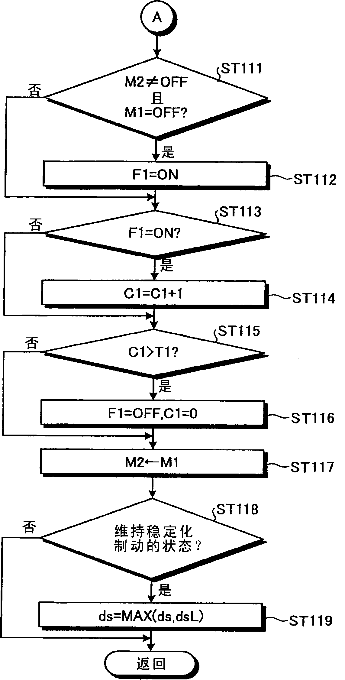
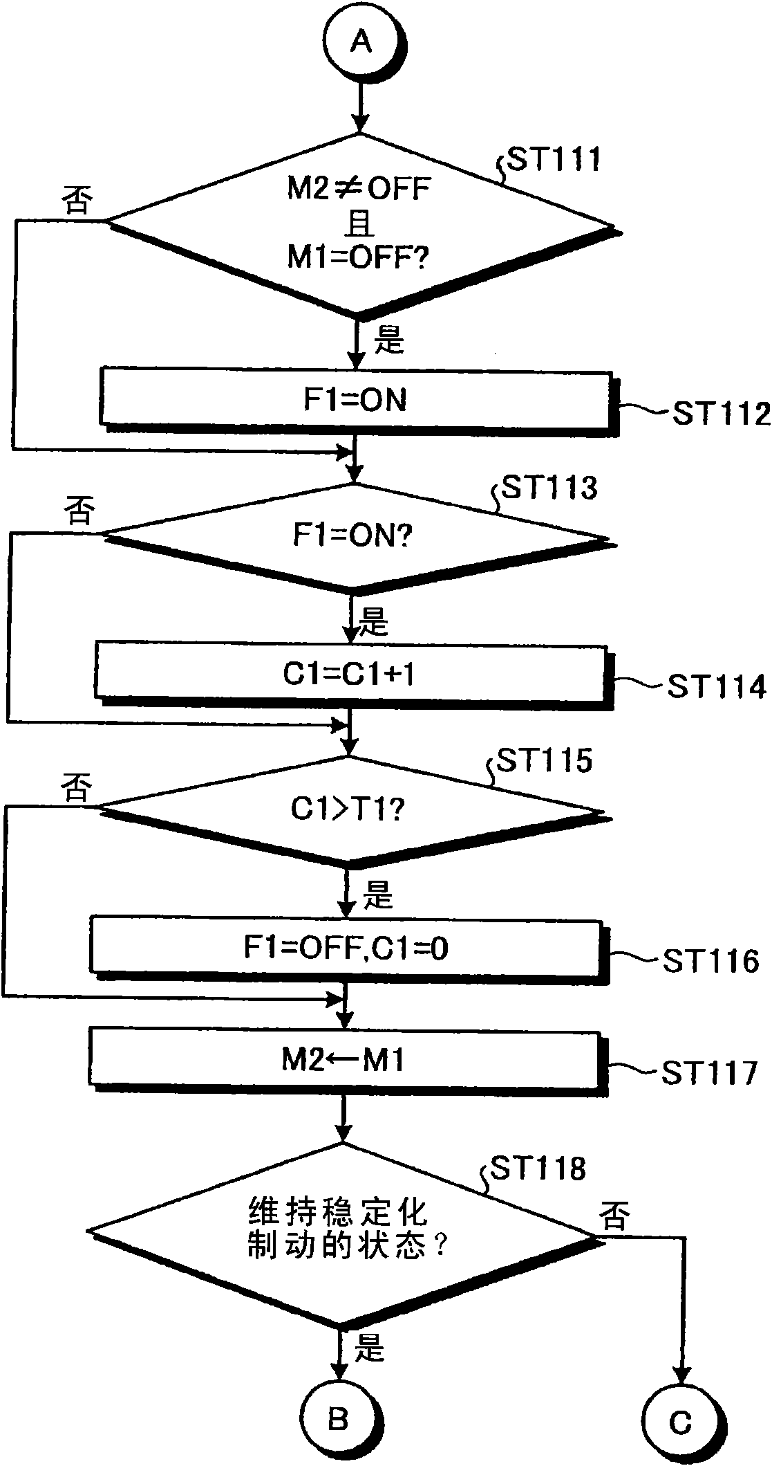
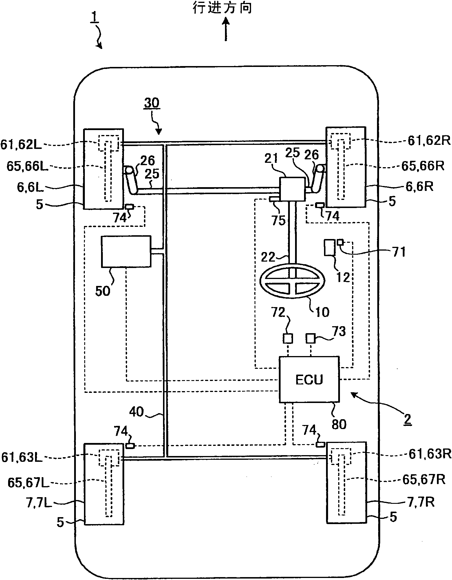
[0081] figure 1 It is a schematic diagram of a vehicle provided with the vehicle behavior control device according to Embodiment 1 of the present invention. The vehicle 1 including the vehicle behavior control device 2 according to Embodiment 1 uses an engine (not shown) as an internal combustion engine as a power source, and the power generated by the power source is transmitted to a plurality of power transmission paths such as a transmission (not shown). One of the wheels 5 is set as a driving wheel. That is, when the vehicle 1 is a front-wheel drive vehicle, the power is transmitted to the front wheels 6, when the vehicle 1 is a rear-wheel drive vehicle, the power is transmitted to the rear wheels 7, and when the vehicle 1 is a four-wheel drive vehicle, the power is transmitted Pass to all wheels 5. Thereby, the driving wheels to which the power is transmitted generate driving force, and the vehicle 1 is installed to be able to travel by the driving force. In addition, th...

Embodiment 2

[0173] The configuration of the vehicle behavior control device 120 according to Embodiment 2 is substantially the same as that of the vehicle behavior control device 2 according to Embodiment 1, but is characterized in that a yaw rate is used as a release condition for stabilized braking. The other configuration is the same as that of the first embodiment, so the description is omitted and the same reference numerals are attached. Image 6 It is a configuration diagram of the main parts of the vehicle behavior control device according to the second embodiment. The vehicle behavior control device 120 according to the second embodiment is configured to be capable of performing stabilized braking when the steering angle of the second steering when the return steering is performed is maintained, and the stabilized braking is performed by the second steering. The braking force is generated on the front wheels 6 in the opposite direction of the steering direction, and the control of ...


PUM


Abstract

A vehicle behavior controlling apparatus includes a steering state determining unit that determines a state of a steering by a driver, and a brake device controlling unit that executes a stabilization braking in which predetermined braking force is generated on a front wheel at a side reverse to a steering direction by a second steering during a turning-back steering, when it is determined that the steering angle in the second steering is held when the turning-back steering is executed by the steering state determining unit, and when it is determined that the steering angle in the second steering is held, a limitation is imposed on an amount of a reduction in the braking force. Thus, a yaw moment in the direction reverse to the yaw moment by the second steering in the turning-back steering can be generated, whereby the yaw moment due to the steering can be reduced.

Description

Technical field [0001] The invention relates to a vehicle behavior control device. In particular, the present invention relates to a vehicle behavior control device that controls the behavior of the vehicle by controlling the braking force generated on the wheels. Background technique [0002] In the past, some vehicle behavior control devices control the braking force generated on the wheels, and control the braking force of the wheels according to the state of the vehicle during driving regardless of the driver's intention, thereby ensuring the stability of the vehicle during driving. As such vehicle behavior control, for example, if the control deviation of the yaw speed exceeds a predetermined threshold during a turning of the vehicle, the yaw speed is reduced by generating braking force on the front wheels outside the turning, thereby stabilizing the behavior. [0003] Here, the brake device used when stabilizing the behavior of the vehicle in this way generates hydraulic pre...

Claims


Application Information

Patent Timeline
Patent Type & Authority Patents(China)
IPC IPC(8): B60T8/1755
CPCB60T8/1755B60T2220/03
Inventor 渡部良知
Owner TOYOTA JIDOSHA KK
Learn More