
Shift controller and shift control method for automatic transmission mechanism

a technology of automatic transmission and shift control, which is applied in the direction of fluid couplings, road transport, couplings, etc., can solve the problems of engine brake force being too large, affecting driving comfort, and causing unplanned deceleration feelings

Inactive Publication Date: 2010-08-19
TOYOTA JIDOSHA KK
View PDF3 Cites 15 Cited by
  • Summary
  • Abstract
  • Description
  • Claims
  • Application Information

AI Technical Summary

Benefits of technology

[0009]The invention provides a shift controller and a shift control method for an automatic transmission mechanism that can ensure the preceding drive state when an engine brake force is increased by a drive resistance of a mechanical hydraulic pump.
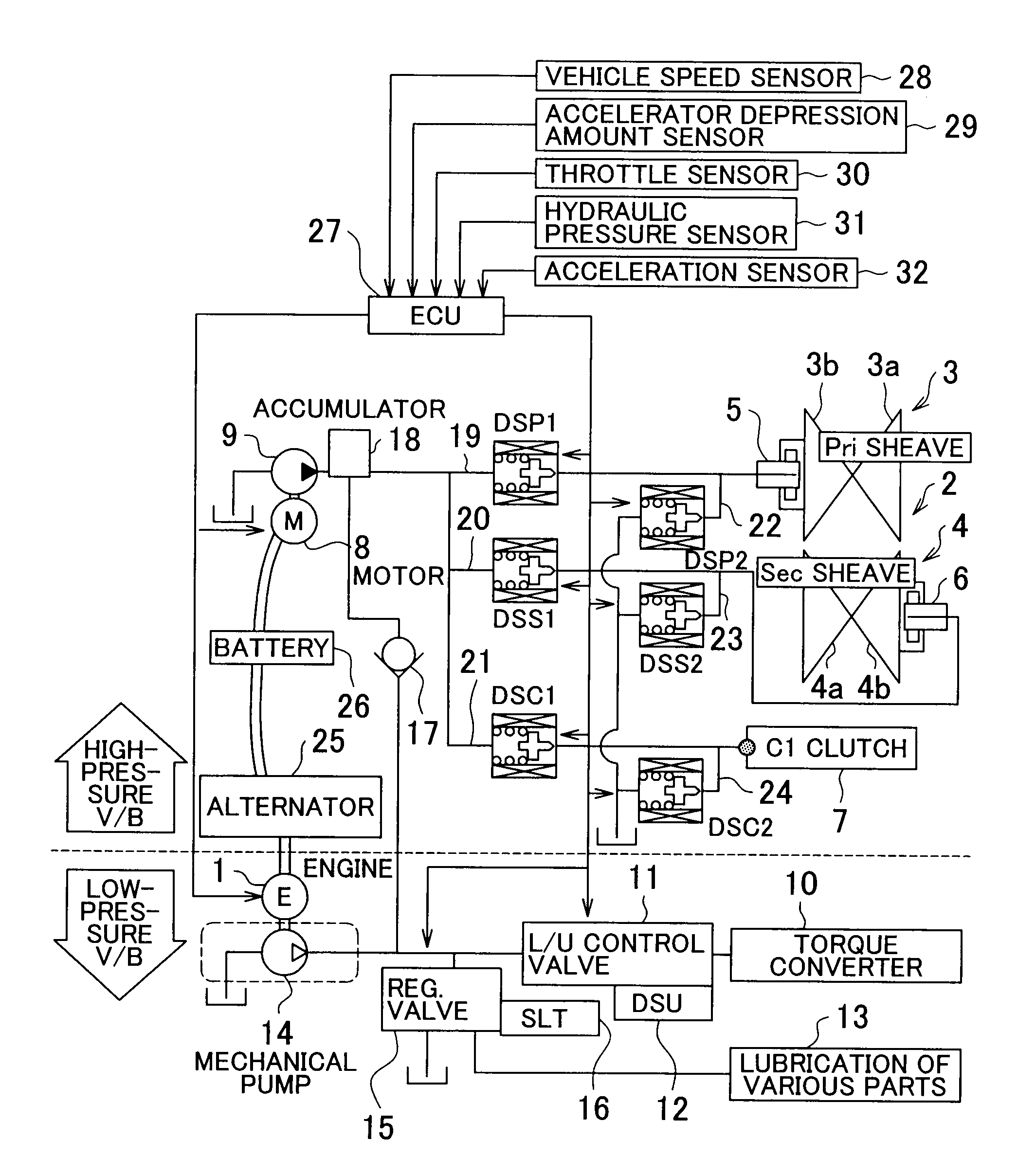
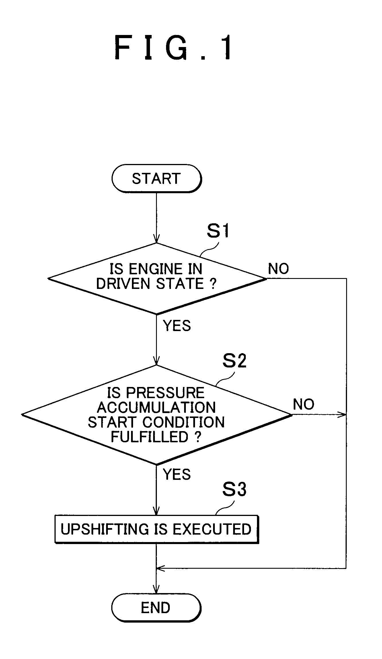
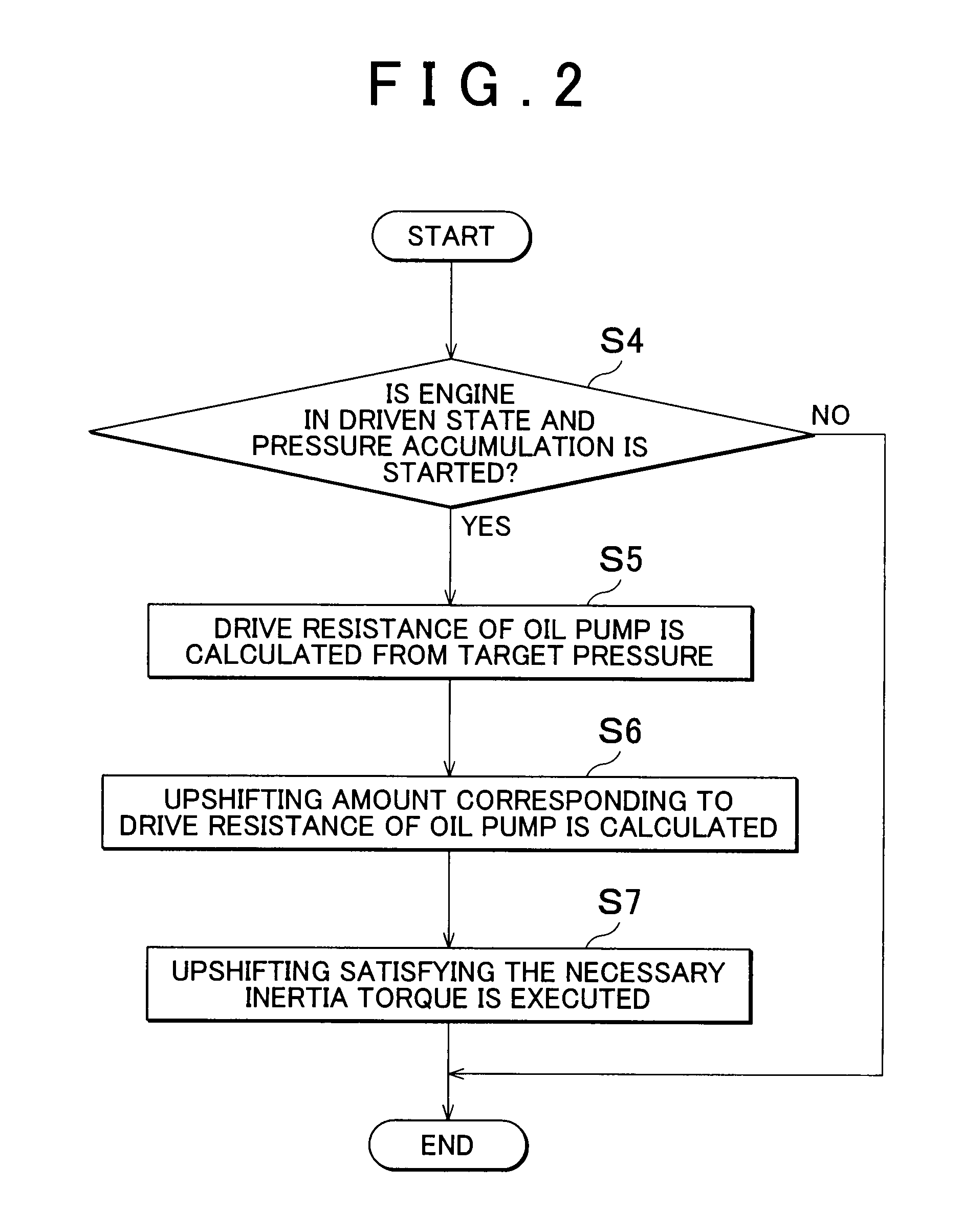
[0010]The first aspect of the invention relates to a shift controller for an automatic transmission mechanism that includes an automatic transmission mechanism for shift transmission of power generated by an engine, a mechanical hydraulic pump that is driven by the engine and generates a relatively low hydraulic pressure, and an accumulator that communicates with the mechanical hydraulic pump and accumulates at least a portion of the hydraulic pressure generated by the mechanical hydraulic pump, and that is configured to perform a control that changes a revolution speed of the engine by controlling a gear ratio of the automatic transmission mechanism, the shift controller including: a driven state determination portion that determines that the engine is in a driven state in which the engine is driven by a travel inertia force; an accumulated pressure amount detection portion that detects that the accumulated pressure amount of the accumulator is equal to or lower than a predetermined value; an accumulated pressure execution portion that increases the hydraulic pressure generated by the mechanical hydraulic pump and that causes the accumulator to accumulate at least a portion of the hydraulic pressure generated by the mechanical hydraulic pump when the engine is determined by the driven state determination portion to be in the driven state and the accumulated pressure amount detection portion detects that the accumulated pressure amount of the accumulator is equal to or lower than the predetermined value; and an upshifting execution portion that reduces a brake force, which is generated when at least a portion of the hydraulic pressure generated by the mechanical hydraulic pump is accumulated in the accumulator, by conducting upshifting that relatively decreases the gear ratio of the automatic transmission mechanism.
[0011]According to the first aspect of the invention, the upshifting is conducted by the upshifting execution portion to decrease relatively the gear ratio of the automatic transmission mechanism in a driven state in which the engine is driven by a travel inertia force or the like when the hydraulic pressure generated by the mechanical hydraulic pump is increased and at least a portion of the hydraulic pressure generated by the mechanical hydraulic pump is accumulated in the accumulator. As a result, hydraulic pressure regeneration can be conducted in the driven state of the engine, control is conducted such that decreases relatively the gear ratio of the automatic transmission mechanism, and the revolution speed of the engine is reduced. Therefore, because the revolution speed of the mechanical hydraulic pump is reduced, the increase in the engine brake force caused by the drive resistance of the mechanical hydraulic pump that occurs when the hydraulic pressure is accumulated in the accumulator can be inhibited or reduced. Furthermore, the generation of the excessively large engine brake force can be inhibited or prevented and drivability can be improved. Furthermore, a drop in the vehicle speed caused by the extra large engine brake force can be inhibited or reduced. Therefore re-acceleration is facilitated and fuel consumption is improved.

Problems solved by technology

However, of this engine brake force, a load generated as the mechanical hydraulic pump is driven can make the engine brake force too large.
Therefore, the engine brake force is increased by an oil pump load, an un-planned deceleration feeling is created, and drivability can be degraded.

Method used


Image

  • Shift controller and shift control method for automatic transmission mechanism
  • Shift controller and shift control method for automatic transmission mechanism
  • Shift controller and shift control method for automatic transmission mechanism

Examples


Embodiment Construction

[0030]The invention will be described below with reference to specific examples thereof. A vehicle (Ve) to which the invention can be applied is a vehicle having an internal combustion engine such as a gasoline engine and a diesel engine (referred to hereinbelow as “engine 1”) or a hybrid vehicle Ve that uses a combination of the engine 1 and an electric motor. The invention can be applied to a shift controller of any such vehicle Ve provided with a mechanical hydraulic pump that is driven by the engine 1, an accumulator to which at least a portion of hydraulic pressure generated by the mechanical hydraulic pump is supplied and which conducts pressure accumulation, and an automatic transmission mechanism configured to be capable of controlling the revolution speed of the engine 1 by controlling the gear ratio.

[0031]FIG. 5 illustrates schematically the configuration of the vehicle Ve to which the invention can be applied. A continuously variable transmission mechanism 2 installed on ...


PUM


Abstract

A shift controller for an automatic transmission mechanism is configured such that when the engine is in a driven state in which the engine is driven by a travel inertia force or the like and an accumulated pressure amount of the accumulator is equal to or less than a predetermined threshold, the excessive engine brake force, which is generated due to the accumulation of at least a portion of the hydraulic pressure generated from the mechanical hydraulic pump in the accumulator, is inhibited or reduced by conducting upshifting that relatively decreases the gear ratio of the automatic transmission mechanism. Therefore, the generation of the excessive engine brake force can be inhibited or reduced even when the engine is in the driven state and pressure accumulation is performed.

Description

INCORPORATION BY REFERENCE[0001]The disclosure of Japanese Patent Application No. 2009-031926 filed on Feb. 13, 2009 including the specification, drawings and abstract is incorporated herein by reference in its entirety.BACKGROUND OF THE INVENTION[0002]1. Field of the Invention[0003]The invention relates to a shift controller and a shift control method for an automatic transmission mechanism configured to be capable of controlling an engine revolution speed by controlling a gear ratio of the automatic transmission mechanism.[0004]2. Description of the Related Art[0005]In a driven mode in which the engine is driven by power inputted from wheels, for example, when a vehicle decelerates, friction in the engine and a mechanical hydraulic pump driven by the engine becomes a load and the so-called engine brake force is generated. However, of this engine brake force, a load generated as the mechanical hydraulic pump is driven can make the engine brake force too large. Japanese Patent Appli...

Claims


Application Information

Patent Timeline
Patent Type & Authority Applications(United States)
IPC IPC(8): B60W10/00F16D31/02B60W10/04B60W10/10B60W10/18F16H59/14F16H59/54F16H61/02F16H61/16
CPCB60W10/11B60W10/24B60W10/30B60W30/18127F16H61/21F16H61/66259Y10T477/6237F16H2061/0034Y02T10/76Y10T477/644Y10T477/621Y10T477/6203Y10T477/6242F16H61/66272
Inventor YOKOKAWA, TAKAHIROHATTORI, YUJIFUJIMURA, SHINYAKAWAKAMI, TAKAHO
Owner TOYOTA JIDOSHA KK
Learn More