Unlock instant, AI-driven research and patent intelligence for your innovation.

Downhole flow control apparatus, operable via surface applied pressure

Inactive Publication Date: 2007-08-16
ABSOLUTE OIL TOOLS
View PDF19 Cites 43 Cited by
  • Summary
  • Abstract
  • Description
  • Claims
  • Application Information

AI Technical Summary

Problems solved by technology

At very high injection rates (thousands of oil field barrels per day), such solids can cause problems by partially blocking the formation into which the fluids are being injected.
While fluid flow can be controlled from the surface of the well, problems arise.
The known art SCSSV design cannot be selectively placed into operating modes which are either sensitive to fluid flow, or insensitive to fluid flow.

Method used


Image

  • Downhole flow control apparatus, operable via surface applied pressure
  • Downhole flow control apparatus, operable via surface applied pressure
  • Downhole flow control apparatus, operable via surface applied pressure

Examples


Embodiment Construction

)

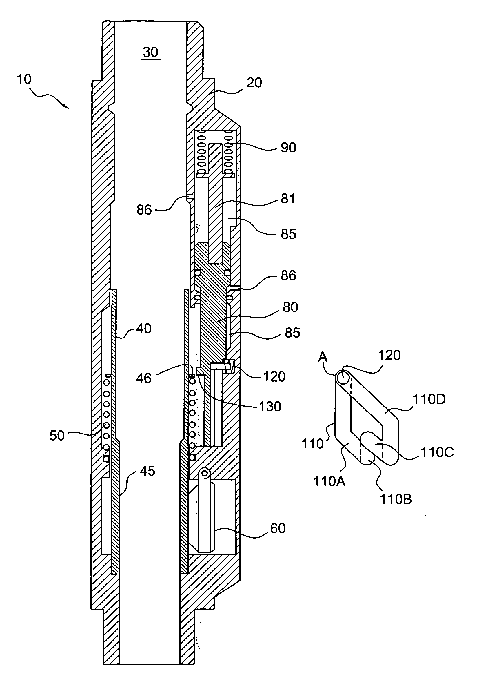
[0017] With reference to the drawings, some of the presently preferred embodiments of the present invention can now be described. It is to be understood that various changes can be made to the invention, without departing from the scope thereof. It is to be further understood that the scope of the invention covers use thereof in any sort of well, e.g. whether production wells or injection wells.

[0018] Broadly speaking, the apparatus may be best understood by considering it as having two broad elements: (1) a valve, comprising a flow tube and flapper; and (2) a lock, comprising a piston responsive to downhole pressure differential (selectively caused by annulus pressure controlled from the surface of the well), and an indexer operatively linked to the piston. The indexer shoulders against the flow tube, so that when the indexer is in a downward position, the flow tube is positively held in said downward position (and as a result, the flapper is blocked open).

[0019] It is to be und...


PUM


Abstract

Flow control apparatus, for placement in a downhole location in the tubing string of a well. The apparatus comprises a valve element and a lock element. Application and removal of annulus pressure (on the annulus between the tubing and the casing) permits the apparatus to be cycled between a sensitive-to-flow mode, in which it opens to permit fluids to be injected down the tubing into a subsurface formation, but closes to prevent fluid backflow from the subsurface formation into the tubing; and an insensitive-to-flow mode, in which the apparatus is open to permit unimpeded fluid flow in either direction.

Description

CROSS REFERENCE TO RELATED APPLICATIONS [0001] This regular patent application claims priority to provisional patent application Ser. No. 60 / 673,500, filed Apr. 22, 2005.BACKGROUND [0002] 1. Field of the Invention [0003] This invention relates generally to apparatus for downhole placement in a wellbore, to control fluid flow through the wellbore. With further specificity, this invention relates to a type of flow control apparatus, particularly suitable for placement in injection wells (that is, wells in which the primary mode of operation is injecting of fluids into a downhole formation), and which can be cycled through different operating modes by application and release of annulus pressure at the surface of the well. [0004] 2. Related Art [0005] Subterranean boreholes, referred to in this application as “wells,” have long been drilled for the production of oil and gas. Wells typically comprise a relatively large diameter tubular string, called casing, which is cemented in a boreho...

Claims


Application Information

Patent Timeline
IPC IPC(8): E21B34/10
CPCE21B23/006E21B34/08E21B2034/005E21B34/102E21B43/16E21B34/10E21B2200/05
Inventor PRINGLE, RONALD E.
Owner ABSOLUTE OIL TOOLS