Method and apparatus for measuring a parameter of a vehicle electrical system

a technology of electrical system and measurement method, which is applied in the direction of impedence measurement, measurement device, instruments, etc., can solve the problems of relatively small cable resistance and typically inability to measur

Inactive Publication Date: 2007-08-23
MIDTRONICS
View PDF99 Cites 54 Cited by
  • Summary
  • Abstract
  • Description
  • Claims
  • Application Information

AI Technical Summary

Problems solved by technology

Because the cable resistance is relatively small it typically cannot be measured using a standard ohm meter or other techniques which are normally used to measure resistance.
However, this is cumbersome and requires components capable of handling the large current.

Method used


Image

  • Method and apparatus for measuring a parameter of a vehicle electrical system
  • Method and apparatus for measuring a parameter of a vehicle electrical system
  • Method and apparatus for measuring a parameter of a vehicle electrical system

Examples


Embodiment Construction

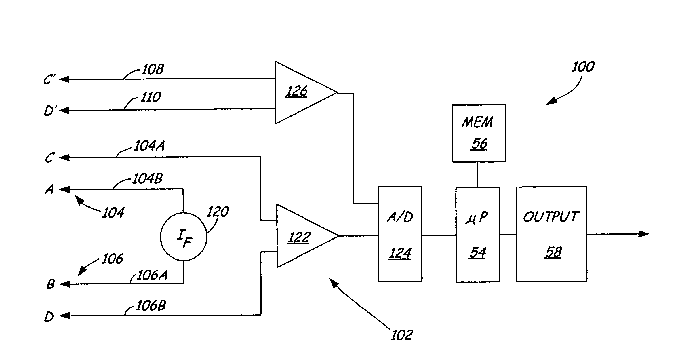
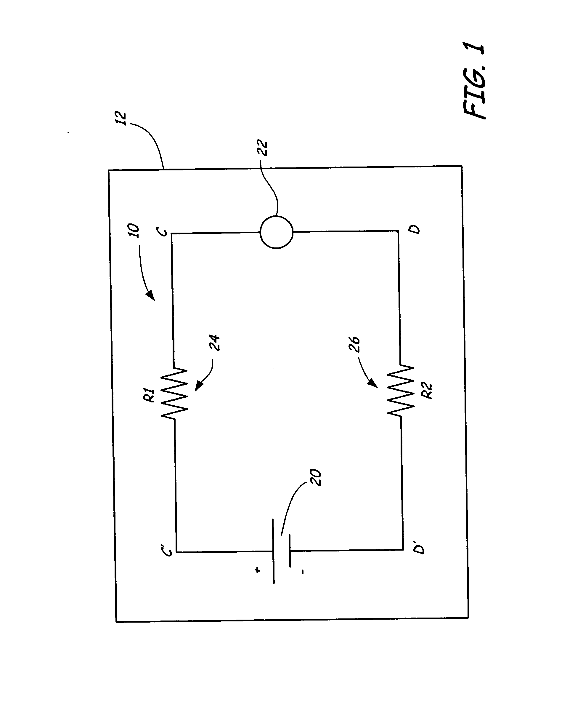
[0011]FIG. 1 is a diagram of an electrical system 10 of large equipment 12 such as a heavy truck. Electrical system 10 includes a battery 20, a high current load 22 and cables 24 and 26. Cables 24 and 26 have resistances R1 and R2, respectively and connect load 22 to battery 20. FIG. 1 also shows connection points C, D and C′, D′. Connections C and D are cross load 22 and connections C′ and D′ are cross battery 20.

[0012] As discussed in the Background section, the resistances R1 and R2 of cables 24 and 26 can have a significant impact on the amount of power which can be delivered to load 22. Even if the resistance values are relatively small, because a relatively large current passes through cables 24 and 26, the resultant voltage drop can significantly reduce the voltage at points C and D and therefore the amount of power (or voltage) which can be delivered to load 22. In industrial equipment, it is often desirable to measure the resistance R1 and R2 of cables 24 and 26, respectiv...


PUM


Abstract

An apparatus for measuring electrical parameters for an electrical system measures a first and second parameters of the electrical system between connections to the electrical system. A processor determines a third electrical parameter of the electrical system as a function of the first parameter and the second parameter.

Description

[0001] The present application is a Divisional of and claims priority of U.S. patent application Ser. No. 10 / 656,526, filed Sep. 5, 2003, the content of which is hereby incorporated by reference in its entirety.BACKGROUND OF THE INVENTION [0002] The present invention relates to the measurement of electrical parameters of a vehicle electrical system. More specifically, the present invention relates to measuring an electrical parameter of an electrical system of a vehicle through the use of multiple measurements. [0003] Electrical systems, such as those which are used in automotive vehicles, consist of a number of discreet components or systems which are interconnected. Techniques for measuring and utilizing parameters, such as dynamic parameters, of electrical systems are shown and disclosed in U.S. Pat. No. 3,873,911, issued Mar. 25, 1975, to Champlin; U.S. Pat. No. 3,909,708, issued Sep. 30, 1975, to Champlin; U.S. Pat. No. 4,816,768, issued Mar. 28, 1989, to Champlin; U.S. Pat. No...

Claims


Application Information

Patent Timeline
Patent Type & Authority Applications(United States)
IPC IPC(8): G01R31/00G01R27/16G01R31/02
CPCG01R27/16G01R31/021G01R31/006G01R31/58
Inventor BERTNESS, KEVIN I.
Owner MIDTRONICS
Why Eureka
Try Eureka