Robot hand having swaying mechanism in library apparatus

a technology of sway mechanism and library, which is applied in the direction of data recording, record carrier guidance, instruments, etc., can solve the problems of inability to establish redundancy and interfere with the transfer of the robot hand, and achieve the effect of reliably allowing the robot hand to reach

Inactive Publication Date: 2007-08-23
FUJITSU LTD
View PDF22 Cites 6 Cited by
  • Summary
  • Abstract
  • Description
  • Claims
  • Application Information

AI Technical Summary

Benefits of technology

[0006] It is accordingly an object of the present invention to provide a library apparatus capable of reliably allowing a robot hand to reach a standby region.
[0009] The transporting mechanism may comprise: a backup carriage; and a backup positioning mechanism designed to position the backup carriage at positions corresponding to the cells within the operating region. The transporting mechanism allows the backup carriage to operate while the aforementioned carriage is inoperative. The backup carriage serves to transport the objects within the cells. The library apparatus thus keeps operating without any interruption.
[0010] The library apparatus may further comprise: a support member mounted on the carriage, the support member moving in the longitudinal direction along a plane between a foremost position and a rearmost position; a support shaft mounted on the support member, the support shaft coupling the grasping fingers to the support member for relative rotation around the rotation axis extending along the plane in the lateral direction perpendicular to the longitudinal direction; and a driving mechanism mounted on the support member, the driving mechanism allowing the grasping fingers to get closer to and distanced from each other in the lateral direction. The library apparatus allows the grasping fingers to catch the object when the support member is set at the foremost position. The object is then taken into the carriage. The carriage can thus transport the object.
[0011] In this case, the library apparatus may further comprise: an elastic member exhibiting a driving force allowing the grasping finger to swing around the support shaft in a specific direction; and a stop designed to position the tip end of the grasping finger at a foremost position in the longitudinal direction when the stop receives the grasping finger rotating in the specific direction. When the stop restricts the rotation of the grasping finger, the grasping finger is forced to take the reference attitude. The tip end of the grasping finger is positioned farthest in the forward direction. When the grasping finger collide against an object on its movement path, the grasping finger rotates around the rotation axis against the elasticity of the elastic member. The grasping fingers is thus allowed to sway around the object. The elasticity of the elastic member serves to keep the grasping finger at the reference attitude unless the grasping finger collide with an object. The grasping fingers are allowed to normally catch the object within the cell. The aforementioned swaying mechanism can be realized in a facilitated manner.

Problems solved by technology

A cell or a magnetic tape cartridge lying on the movement path of the grasping fingers may interfere with the transfer of the robot hand.
Redundancy cannot be established.

Method used


Image

  • Robot hand having swaying mechanism in library apparatus
  • Robot hand having swaying mechanism in library apparatus
  • Robot hand having swaying mechanism in library apparatus

Examples


Embodiment Construction

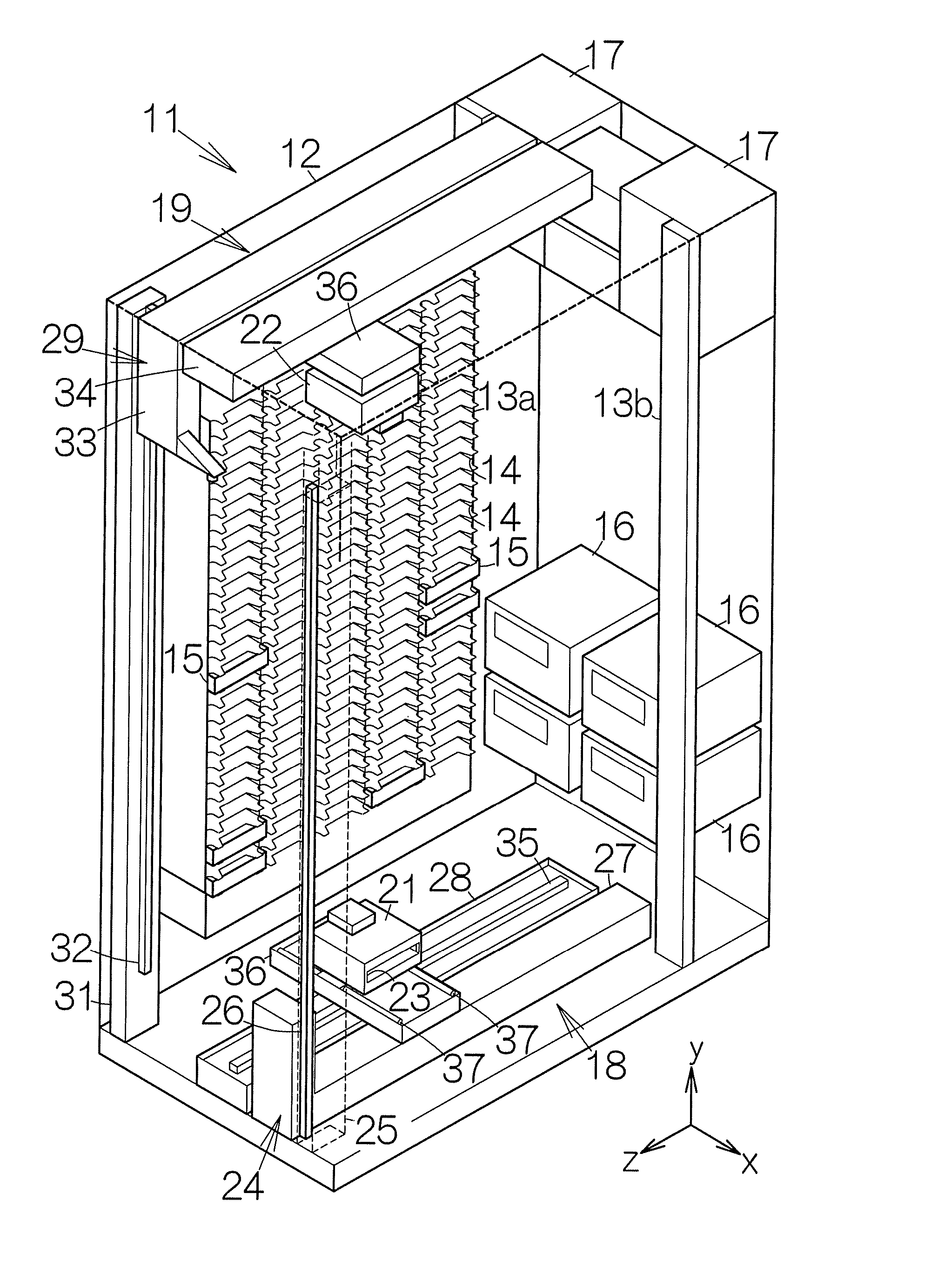
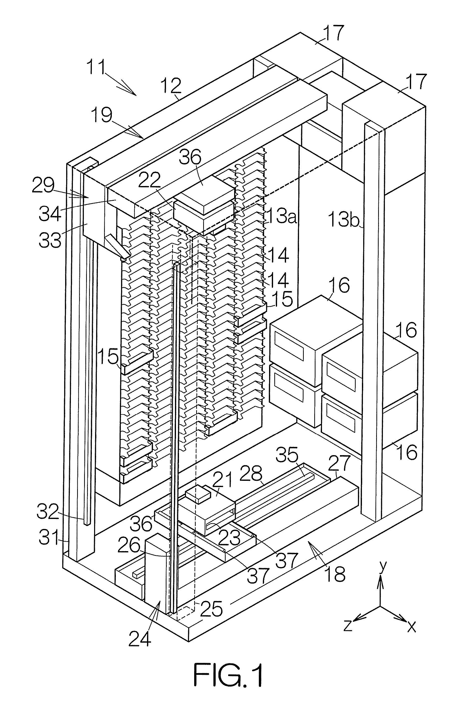
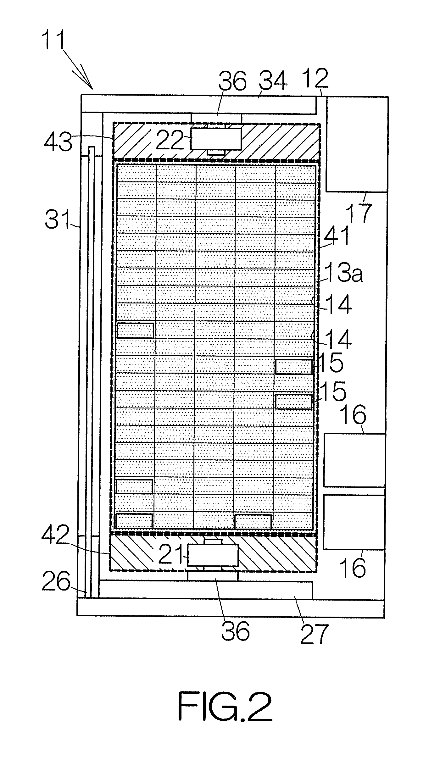
[0031]FIG. 1 schematically illustrates the structure of a magnetic tape library apparatus 11 according to an embodiment of the present invention. The magnetic tape library apparatus 11 includes a box-shaped enclosure 12. The enclosure 12 defines an inner space in the form of a parallelepiped standing upright from the floor, for example. Storage boxes 13a, 13b are placed within the inner space of the enclosure 12. A pair of storage boxes 13a, one of them not shown, is located at opposite sides of a predetermined central space in the form of a parallelepiped. Each of the storage boxes 13a includes cells 14, 14, . . . . The openings of the cells 14, 14, . . . are arranged along planes perpendicular to the floor, namely side surfaces of the central space. An object or recording medium such as a magnetic tape cartridge 15 is contained in the individual cell 14. A linear tape-open (LTO) cartridge may be employed as the magnetic tape cartridge 15, for example.

[0032] The storage box 13b is...


PUM


Abstract

A library apparatus includes cells. A positioning mechanism serves to position a carriage relative to the cells within an operating region adjacent to a standby region. A transporting mechanism drives the carriage toward the standby region. A swaying mechanism allows grasping fingers on the carriage to go around an object lying on the movement path of the grasping fingers when the transporting mechanism carries the carriage to the standby region. The grasping fingers acts to hold an object within the cell. If the positioning mechanism malfunctions, the transporting mechanism transfers the carriage to the standby region. Even if an object exits on the movement path of the grasping finger, the carriage is allowed to keep moving because the swaying mechanism allows the grasping finger or fingers to sway around the object on the movement path. The carriage thus reliably reaches the standby region.

Description

BACKGROUND OF THE INVENTION [0001] 1. Field of the Invention [0002] The present invention relates to a library apparatus such as a magnetic tape library apparatus, for example. In particular, the present invention relates to a robot hand capable of accessing to a cell containing an object such as a magnetic tape cartridge in the library apparatus. [0003] 2. Description of the Prior Art [0004] The robot hand is positioned at a specific position corresponding to one of cells within an operating region adjacent to a standby region in the magnetic tape library apparatus. Grasping fingers are mounted on the robot hand. The grasping fingers grasp a magnetic tape cartridge within the cell. The robot hand is designed to transport a magnetic tape cartridge in the magnetic tape library apparatus. [0005] When the robot hand malfunctions, the robot hand is transferred to the standby region. A cell or a magnetic tape cartridge lying on the movement path of the grasping fingers may interfere with...

Claims


Application Information

Patent Timeline
Patent Type & Authority Applications(United States)
IPC IPC(8): B65G1/00
CPCG11B17/225G11B15/6835G11B15/675G11B15/66G11B15/67G11B15/68
Inventor ISHIYAMA, KAZUNORI
Owner FUJITSU LTD
Why Eureka
Try Eureka