Integrated micro fuel cell apparatus

a fuel cell and micro-chip technology, applied in the field of micro-chip fuel cell apparatus, can solve the problems of limited energy stored in the battery, major inconvenience of the battery, and limited amount of stored energy

Inactive Publication Date: 2007-08-30
MOTOROLA INC
View PDF5 Cites 19 Cited by
  • Summary
  • Abstract
  • Description
  • Claims
  • Application Information

AI Technical Summary

Problems solved by technology

The energy stored in the batteries is limited.
The limited amount of stored energy and the frequent recharging are major inconveniences with the batteries.
However, the energy generated by these methods is small, usually only a few milliwatt's, and it requires a large volume to generate sufficient power in the hundred of milliwatts needed, making it unattractive for cell phone type applications.
However, the power densities are low with this approach, and also there are safety concerns with the radioactive materials.
This is an attractive power source for remote sensor type applications, but not for cell phone power sources.
Fuel cells with active control systems and high operating temperature fuel cells such as active control direct methanol or formic acid fuel cells (DMFC or DFAFC), reformed hyd

Method used


Image

  • Integrated micro fuel cell apparatus
  • Integrated micro fuel cell apparatus
  • Integrated micro fuel cell apparatus

Examples


Embodiment Construction

[0013] The following detailed description of the invention is merely exemplary in nature and is not intended to limit the invention or the application and uses of the invention. Furthermore, there is no intention to be bound by any theory presented in the preceding background of the invention or the following detailed description of the invention.

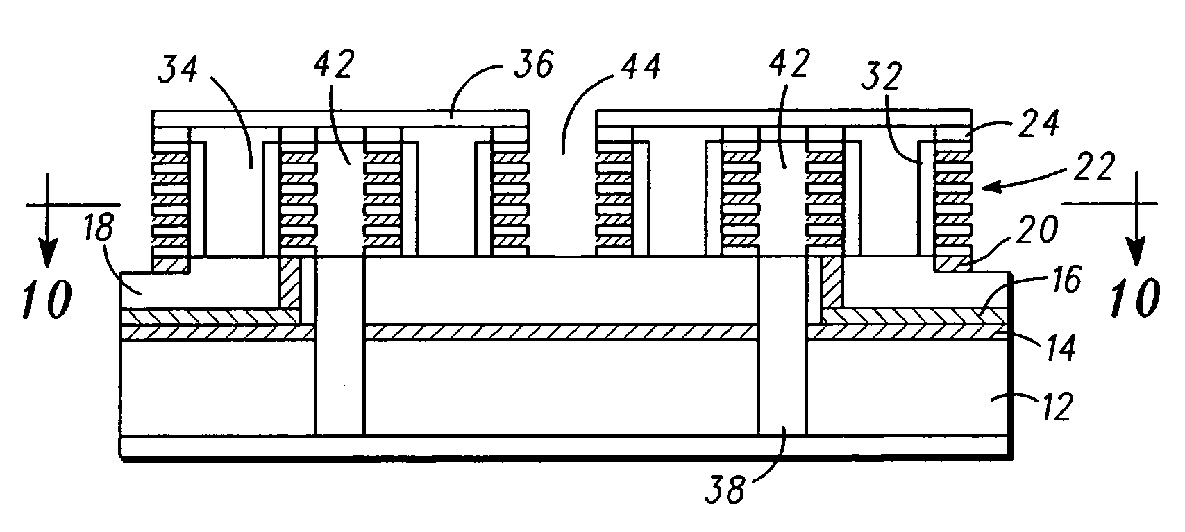
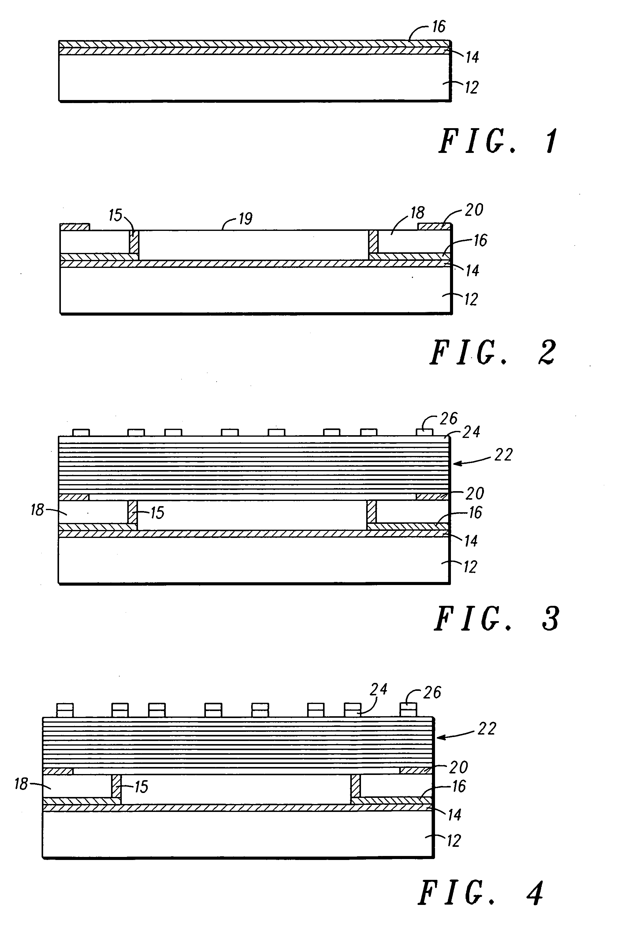
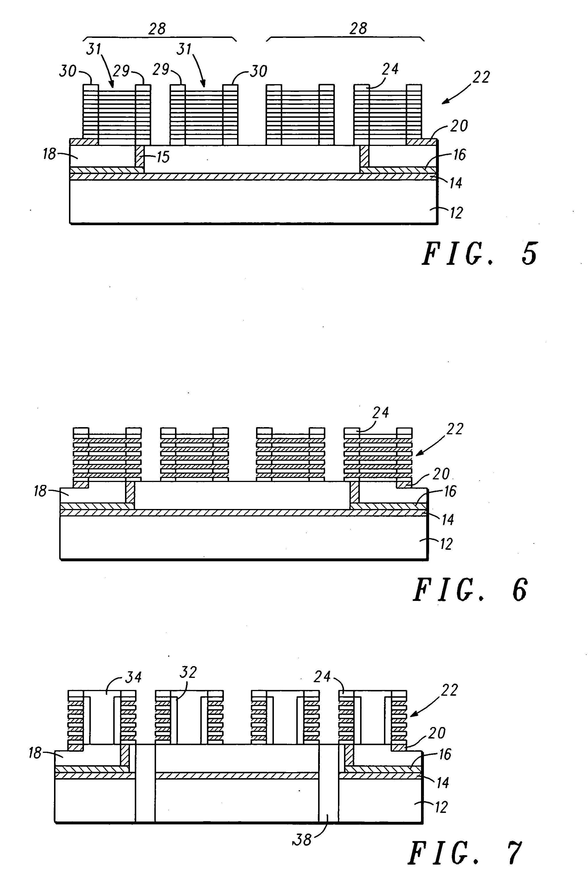
[0014] Main components of a micro fuel cell device are a proton conducting electrolyte separating the reactant gases on the anode and cathode regions, an electrocatalyst which helps in the oxidation and reduction of the gas species at the anode and cathode regions of the fuel cell, a gas diffusion layer to provide uniform reactant gas access to anode and cathode regions, and a current collector for efficient collection of electrons and transport them to a load connected across the fuel cell. In the fabrication of the micro fuel cell structures, conductive porous metal layers can be used for gas diffusion as well as for current collection. ...


PUM


Abstract

A micro fuel cell and method of forming such includes depositing multiple layers (22) of alternating metals over a substrate (12); etching at least one metal from the multiple layers (22) creating a void between the remaining layers; forming a plurality of pedestals (28) in the multiple layers (22), each pedestal (28) having a center anode (29) portion and a concentric cathode (31) portion separated by a concentric cavity (31); filling the concentric cavity (31) with an electrolyte; and capping the center anode (29) portion and the concentric cavity (31).

Description

FIELD OF THE INVENTION [0001] The present invention generally relates to micro fuel cells, and more particularly to a micro fuel cell apparatus integrated on silicon. BACKGROUND OF THE INVENTION [0002] Rechargeable batteries are the primary power source for cell phones and various other portable electronic devices. The energy stored in the batteries is limited. It is determined by the energy density (Wh / L) of the storage material, its chemistry, and the volume of the battery. For example, for a typical Li ion cell phone battery with a 250 Wh / L energy density, a 10 cc battery would store 2.5 Wh of energy. It could last for a few hours to a few days depending on the usage. Recharging always requires an electrical outlet. The limited amount of stored energy and the frequent recharging are major inconveniences with the batteries. There is a need for a longer lasting, easily recharging solution for cell phone power sources. One approach to fulfill this need is to have a hybrid power sour...

Claims


Application Information

Patent Timeline
IPC IPC(8): H01M8/02H01M8/10
CPCH01M8/1004Y02E60/521H01M2008/1095H01M8/1097Y02E60/50H01M8/02H01M8/10H01M8/18
Inventor D'URSO, JOHN J.BAKER, JEFFREY H.KORIPELLA, CHOWDARY R.
Owner MOTOROLA INC
Why Eureka
Try Eureka