Electric Motor

a technology of electric motors and motors, applied in the direction of generators/motors, magnetic circuit rotating parts, magnetic circuit shapes/forms/construction, etc., can solve the problem that the effect is not always obtained in suppression, and achieve the effect of reducing the number of parts, reducing the cogging torque, and reducing the unbalance for

Active Publication Date: 2007-09-06
HITACHI LTD +1
View PDF7 Cites 45 Cited by
  • Summary
  • Abstract
  • Description
  • Claims
  • Application Information

AI Technical Summary

Benefits of technology

[0017] However, Patent Document 1 is effective in reduction in the cogging torque, reduction in the unbalance force, and reduction in the number of parts, though the effect in reduction in vibration and noise due to the electromagnetic exciting force in the radial direction is low.

Problems solved by technology

However, an effect is not always obtained in suppression of the longitudinal bending deformation mode of the stator induced by the electromagnetic exciting force in the radial direction of an internal rotation motor.

Method used


Image

  • Electric Motor
  • Electric Motor
  • Electric Motor

Examples


Embodiment Construction

Description of the Preferred Embodiments

[0047] Hereinafter, the embodiments of the present invention will be explained with reference to the accompanying drawings.

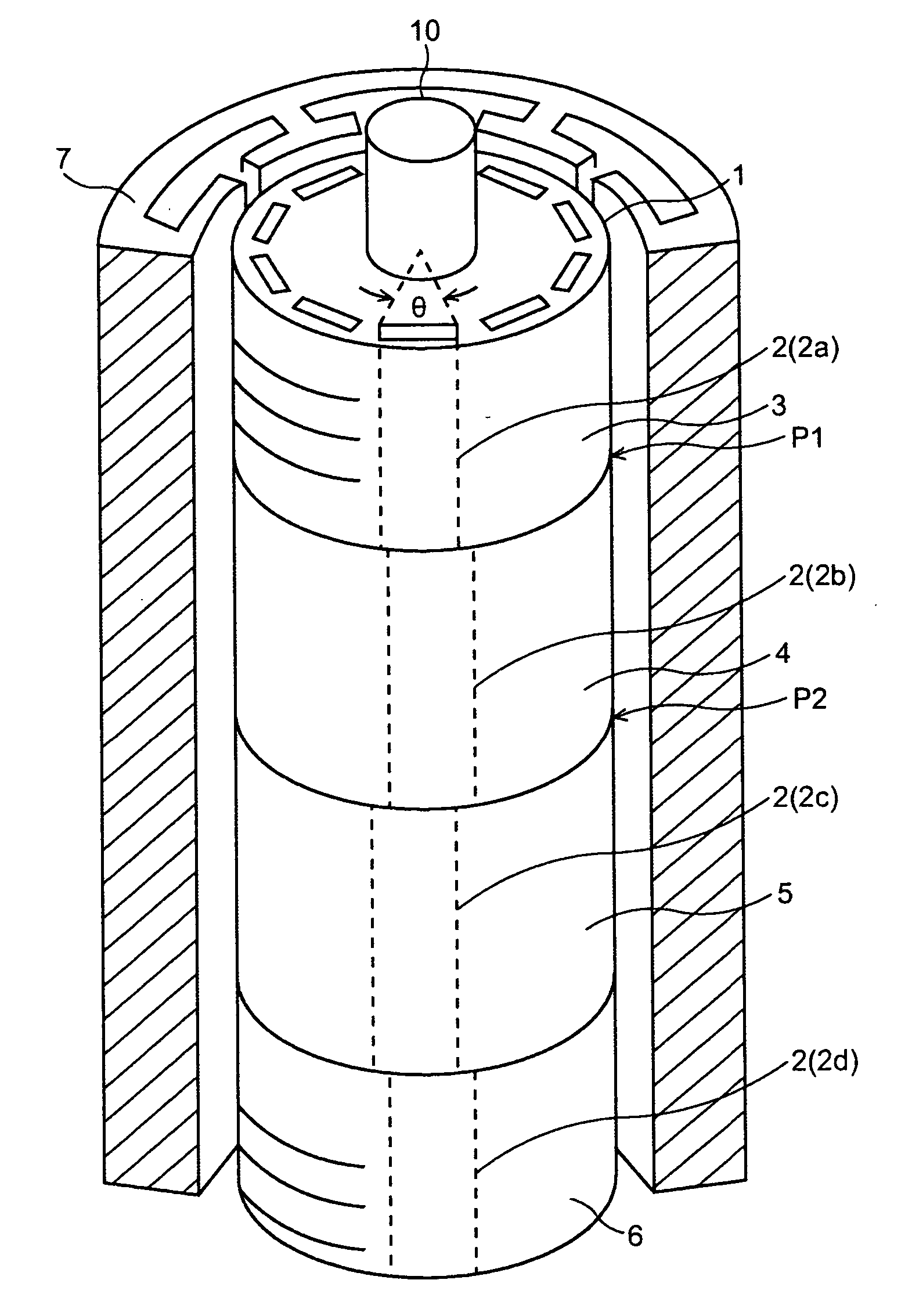
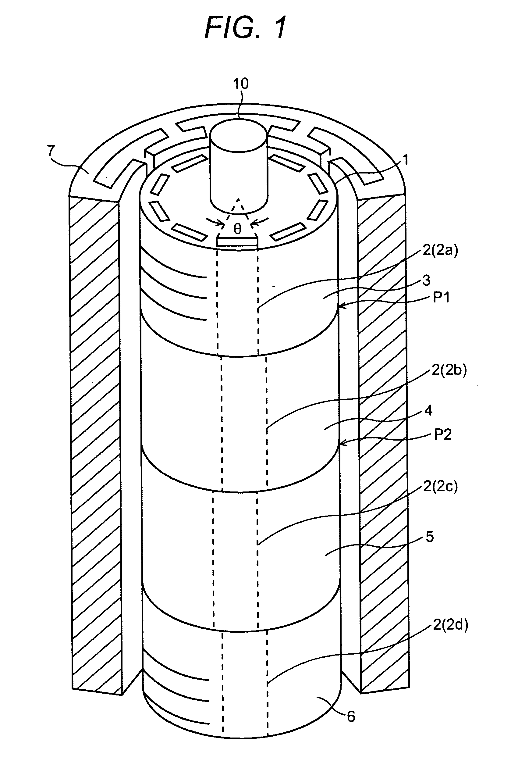
[0048]FIG. 1 is a drawing showing an embodiment of a rotor and a stator 7 in an example of a permanent magnet motor of an electric motor 100 of the present invention. FIG. 3 shows a conceptual diagram of the stator core (stator) 7, and FIG. 3(a) shows the cylindrical shape, and FIG. 3(b) shows the section 8 thereof. In these drawings, the core of the rotor 1 is composed of laminated steel plates and the laminated steel plates are divided into a plurality of blocks in the axial direction, that is, rotor pieces. The rotor 1 shown in FIG. 1 is composed of four rotor pieces 3, 4, 5, and 6, a shaft 10, and permanent magnets 2 (2a, 2b, 2c, 2d) having the same axial length as the axial length of the rotor pieces 3, 4, 5, and 6 in the axial direction. The permanent magnets 2 respectively have an effective pole opening angle of θ...


PUM


Abstract

The vibration and noise excited by the electromagnetic exciting force in the radial direction of an electric motor are suppressed.
In an electric motor 100, a rotor 1 is divided into four rotor pieces 3, 4, 5, and 6 for an axial length of 2L of one group of the rotor core, and for example, the four rotor pieces 3, 4, 5, and 6 are ideally 0.29L, 0.71L, 0.71L, and 0.29L in axial length in the axial direction, and permanent magnets 2 of the rotor pieces 3, 4, 5, and 6 are arranged in the circumferential direction so that the phase differences of the electrical angle are 0, π, 0, and π. Further, when an effect is obtained even if the ideal axial length is changed, the tolerance of the aforementioned axial length is ±0.1L.

Description

BACKGROUND OF THE INVENTION [0001] 1. (Field of the Invention) [0002] The present invention relates to an electric motor and more particularly to a structure for suppressing generation of electromagnetic vibration and noise caused by electromagnetic exciting force in the radial direction of an inverter motor. [0003] 2. (Prior Art) [0004] Many electric motors are used in household electric appliances and various office automation devices and furthermore in recent years, have been loaded in electric cars. [0005] The motors are required for large output power, thus vibration and noise due to electromagnetic exciting force are caused. [0006] The electromagnetic exciting force in the radial direction is generated when, during mutual movement of a rotor and a stator, the electromagnetic path of magnetic field flux generated from the magnetic poles of the rotor is periodically changed whenever the magnetic poles of the rotor cross the openings of the slots formed on the stator and the magn...

Claims


Application Information

Patent Timeline
Patent Type & Authority Applications(United States)
IPC IPC(8): H02K16/02H02K21/12H02K19/20H02K16/00H02K1/18H02K1/27H02K21/14H02K29/03
CPCH02K2201/06H02K29/03H02K1/165H02K1/187H02K1/27
Inventor NEMOTO, KANAKOTAKANO, YASUSHITAKAGI, MICHIYUKITAJIMA, FUMIONEZU, AKIRAYAMAZAKI, TSUKASAOOKI, SHUNJIKIMURA, MASAHIDEFUJITA, YASUSHI
Owner HITACHI LTD
Why Eureka
Try Eureka