Pressure balancing type high-precision high-pressure-difference control valve

A balanced, high-precision technology, applied in the direction of valve lift, valve device, valve details, etc., can solve the problems of low adjustment performance and adjustment accuracy, poor adjustment performance and accuracy, easy damage to the flow window, etc., to achieve energy consumption, The effect of controlling flow speed and preventing valve clogging

Pending Publication Date: 2019-03-01
WUZHONG INSTR +1
View PDF0 Cites 3 Cited by
  • Summary
  • Abstract
  • Description
  • Claims
  • Application Information

AI Technical Summary

Problems solved by technology

[0002] At present, there are many structural designs for valves for high-pressure differential media, such as multi-layer sleeve type, axial multi-stage string type, labyrinth type, etc., but the multi-layer sleeve type can only meet the control of small pressure differences, and the flow window It is extremely easy to damage and has a short service life; although the axial multi-stage series decompression structure has relatively good decompression performance and anti-blocking ability, its adjustment performance and adjustment accuracy are relatively low. The requirements are very high, and it is easy to cause strong vibration in the face of high-pressure differential media, and it is difficult to meet its adjustment requirements for high-precision control occasions; the labyrinth decompression ability is the most prominent, but it has higher requirements for the cleanliness of the media. The usual flow characteristics can only be designed to be approximately linear, and the regulation performance and accuracy are poor

Method used


Image

  • Pressure balancing type high-precision high-pressure-difference control valve
  • Pressure balancing type high-precision high-pressure-difference control valve
  • Pressure balancing type high-precision high-pressure-difference control valve

Examples


Embodiment Construction

[0020] The present invention will be described in detail in conjunction with accompanying drawing now. This figure is a simplified schematic diagram only illustrating the basic structure of the present invention in a schematic manner, so it only shows the components relevant to the present invention.

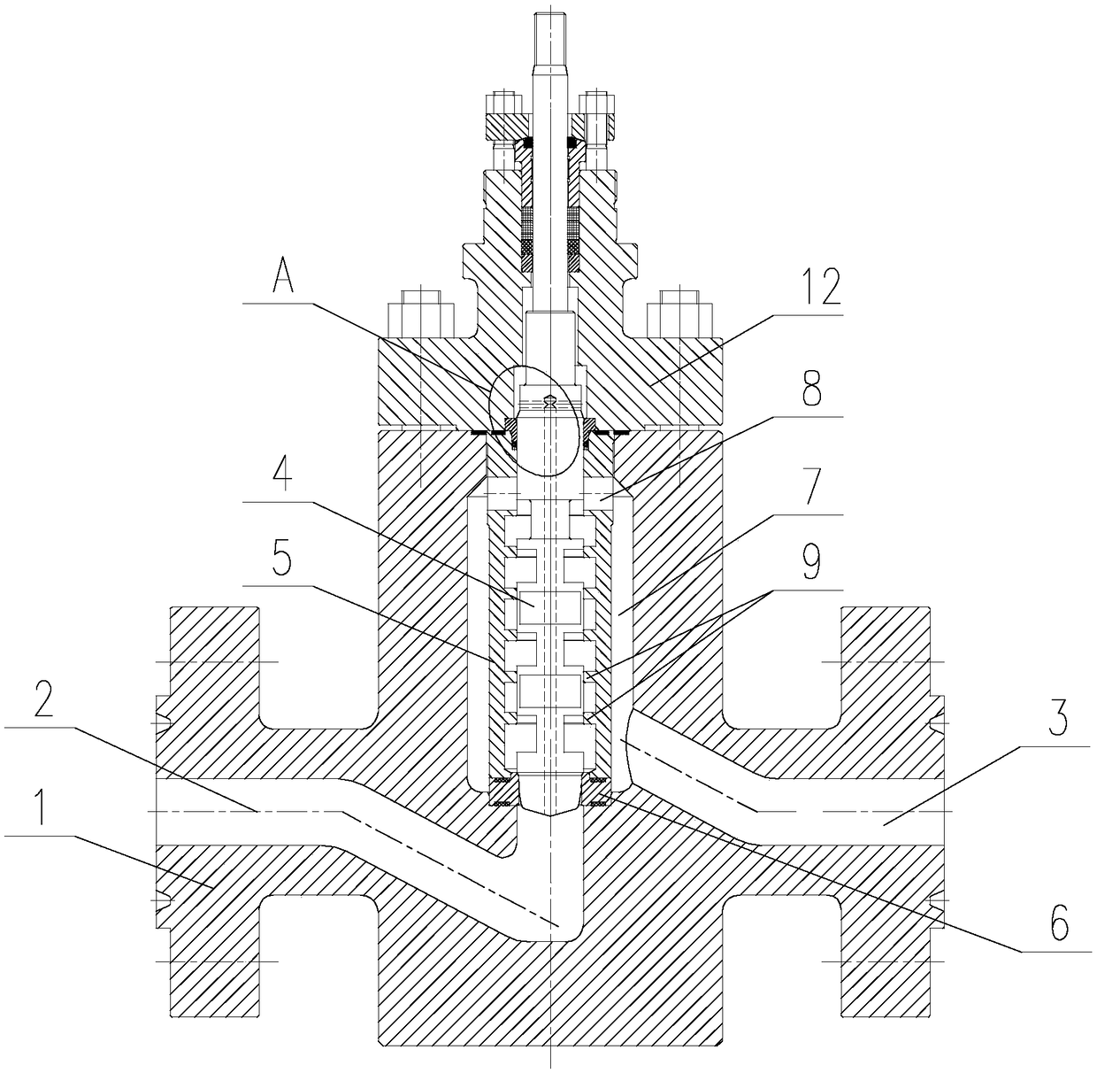
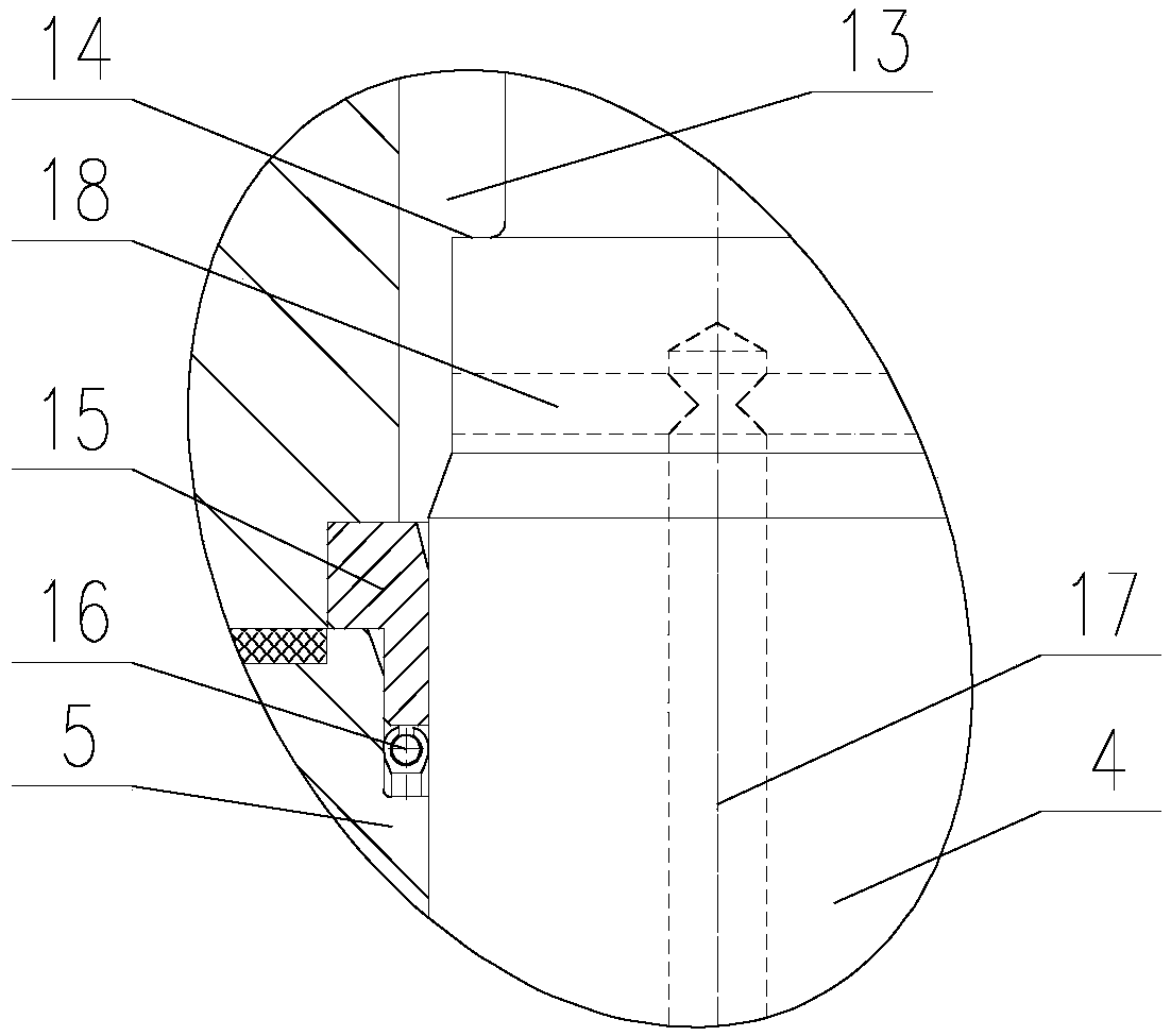
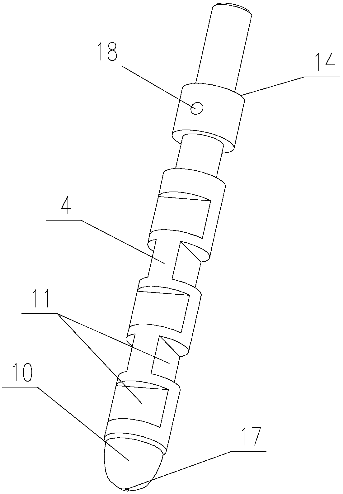
[0021] Such as Figure 1-7 As shown, a pressure-balanced high-precision high-pressure differential control valve of the present invention includes a valve body 1 and a decompression passage arranged in the valve body 1. The inlet 2 and the outlet 3 connected by the channel, the decompression channel is composed of a valve core 4, a valve core sleeve 5 and a valve seat 6, the valve core sleeve 5 is vertically arranged in the valve body 1, and the valve core A discharge channel 7 is provided between the sleeve 5 and the valve body 1, and the upper end of the valve core sleeve 5 is provided with a discharge port 8 communicating with the discharge channel 7, and the discharge chann...


PUM


Abstract

The invention provides a pressure balancing type high-precision high-pressure-difference control valve which comprises a valve body and a pressure reducing channel. An inlet and an outlet are formed in the two sides of the valve body. The pressure reducing channel is composed of a valve core, a valve core sleeve and a valve base. A drainage runner is arranged between the valve core sleeve and thevalve body. A drainage opening communicating with the drainage runner is formed in the upper end of the valve core sleeve. The drainage runner communicates with the outlet. Multiple ring-shaped bossesare arranged on the inner wall face of the valve core sleeve at intervals. The valve base is arranged at the lower end of the valve core sleeve and communicates with the inlet. The valve core is arranged in the valve core sleeve and connected with the valve core sleeve in a sliding manner. A curved surface sealing face matched with the valve base is arranged at the lower end of the valve core. The valve core is provided with multiple buffering sets at intervals in the axial direction. Each buffering set comprises two buffering grooves arranged symmetrically. The adjacent buffering sets are arranged in a staggering manner. When the curved surface sealing face is matched with the valve base, the buffering grooves and the ring-shaped bosses are partially overlapped. According to the controlvalve, the valve core, the valve core sleeve and the valve base are adopted, control over high-pressure-difference media is achieved, adjusting performance is good, and adjusting precision is high.

Description

technical field [0001] The invention relates to the technical field of valves, in particular to a pressure-balanced high-precision high-pressure differential control valve. Background technique [0002] At present, there are many structural designs for valves for high-pressure differential media, such as multi-layer sleeve type, axial multi-stage string type, labyrinth type, etc., but the multi-layer sleeve type can only meet the control of small pressure differences, and the flow window It is extremely easy to damage and has a short service life; although the axial multi-stage series decompression structure has relatively good decompression performance and anti-blocking ability, its adjustment performance and adjustment accuracy are relatively low. The requirements are very high, and it is easy to cause strong vibration in the face of high-pressure differential media, and it is difficult to meet its adjustment requirements for high-precision control occasions; the labyrinth...

Claims


Application Information

Patent Timeline
Patent Type & Authority Applications(China)
IPC IPC(8): F16K39/02F16K47/04F16K1/36
CPCF16K39/02F16K1/36F16K47/04
Inventor 马玉山常占东罗先念李虎生石月娟马佳庆
Owner WUZHONG INSTR
Why Eureka
Try Eureka