Complex mirror projection display

Active Publication Date: 2007-09-06
FAKESPACE LABS
View PDF6 Cites 2 Cited by
  • Summary
  • Abstract
  • Description
  • Claims
  • Application Information

AI Technical Summary

Benefits of technology

[0012] An optimized complex mirror surface allows a rear projection imaging system to be low cost, have high picture quality, and yet still have a shallow cabinet design. The use of a mirror as an optical element decreases the cost and complexity of the projector's optics. The optimal complex mir

Problems solved by technology

Reasonable manufacturing tolerances, cost, and optical limits, however, restrict the depth a rear projection monitor may achieve.
One such optical limit is due to the high image magnification necessary to project images and the short distance, generally less than two feet, available to perform the magnification.
These lenses are expensive and complicated.
Consumers do not want to buy rear projection imaging systems that display warped, distorted, dim, or discolored images.
Designers therefore spend a significant amount of time optimizing image quality given other design constraints, such as cabinet depth, system cost, and others.
Even in rear projection imaging systems using mirrors to lengthen the optical light path distance, these lenses are still very expensive to both design and manufacture, sometimes containing up to twenty-six elements.
It is nearly impossible to produce a co

Method used


Image

  • Complex mirror projection display
  • Complex mirror projection display
  • Complex mirror projection display

Examples


Example

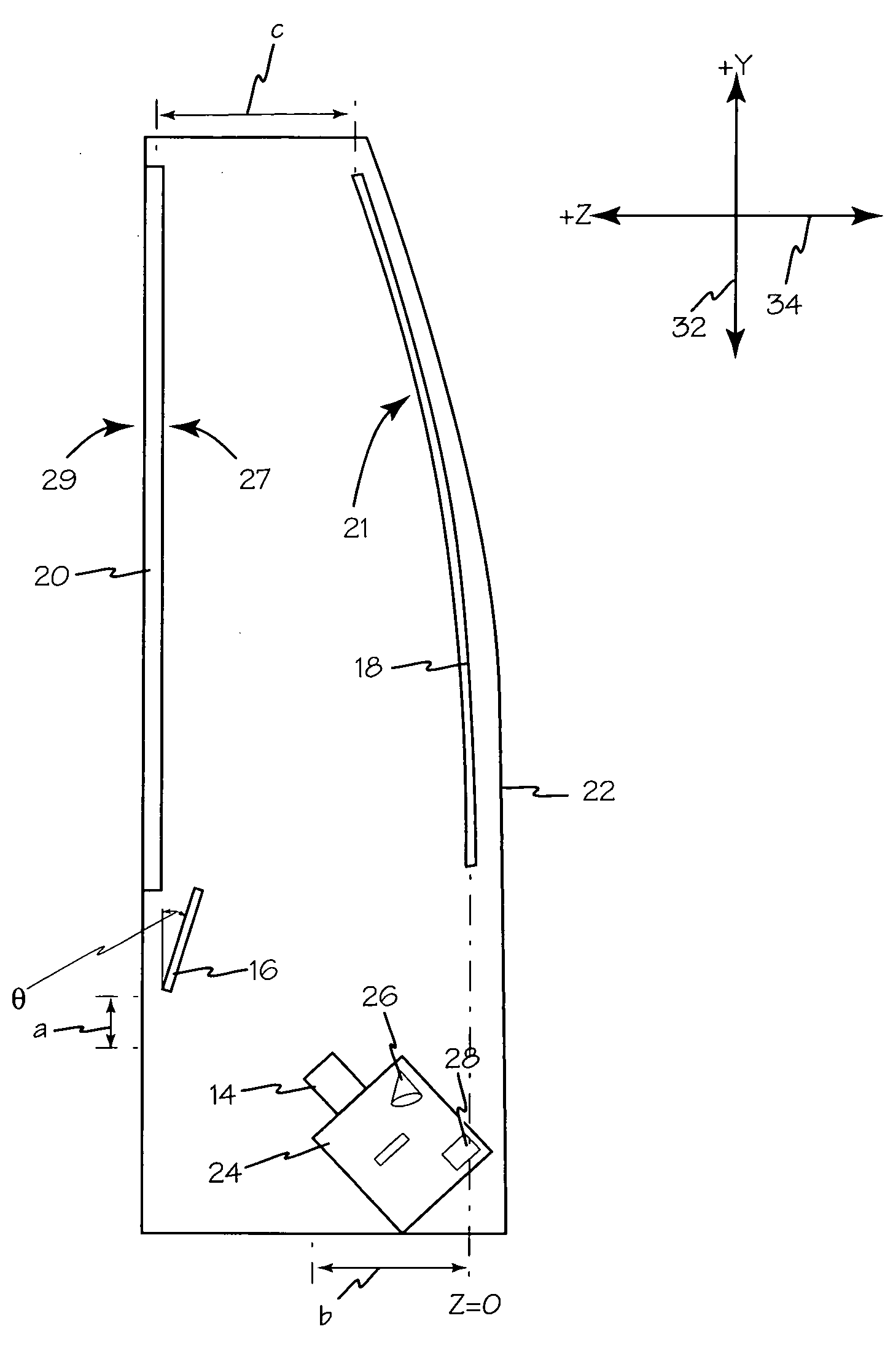
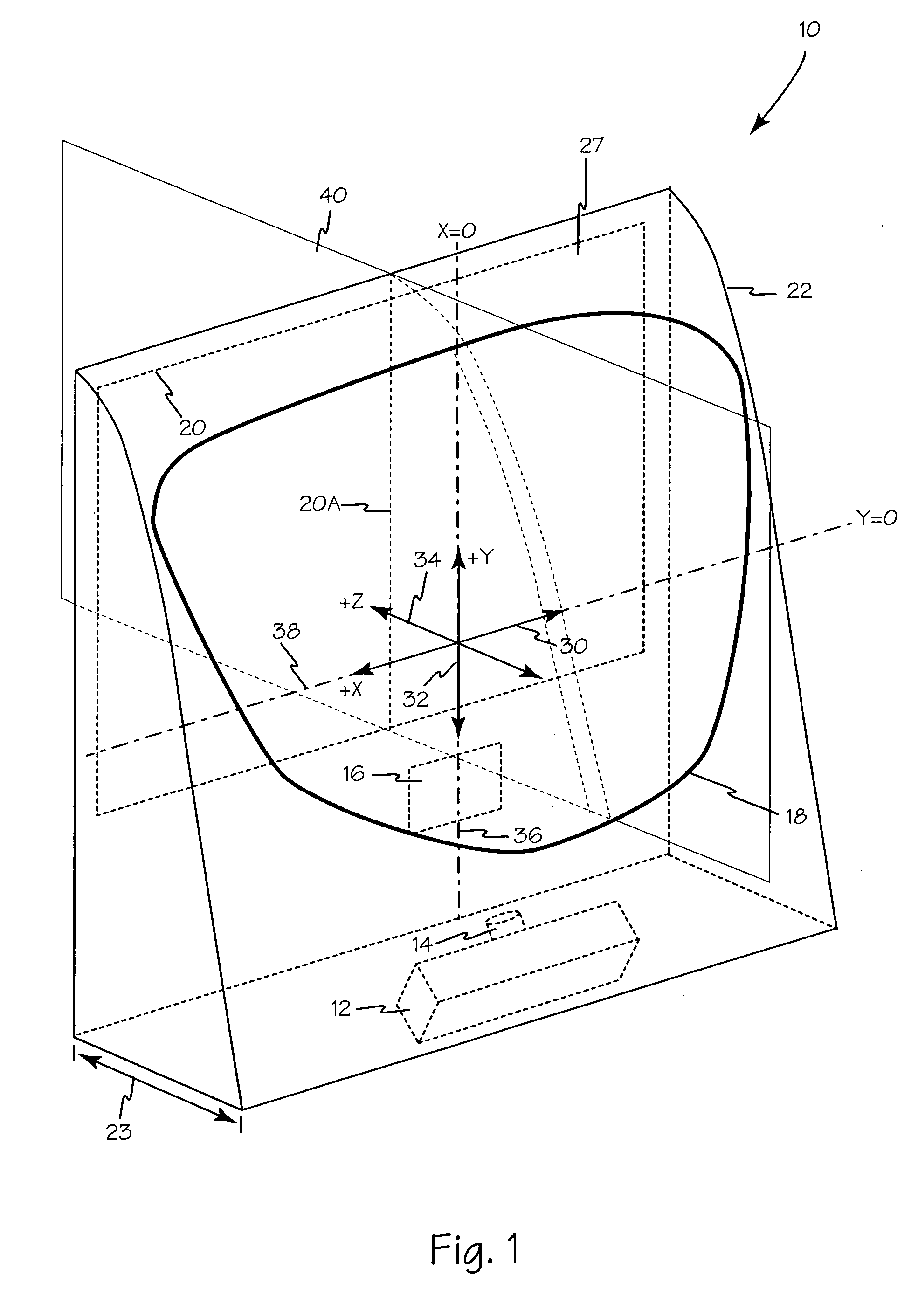
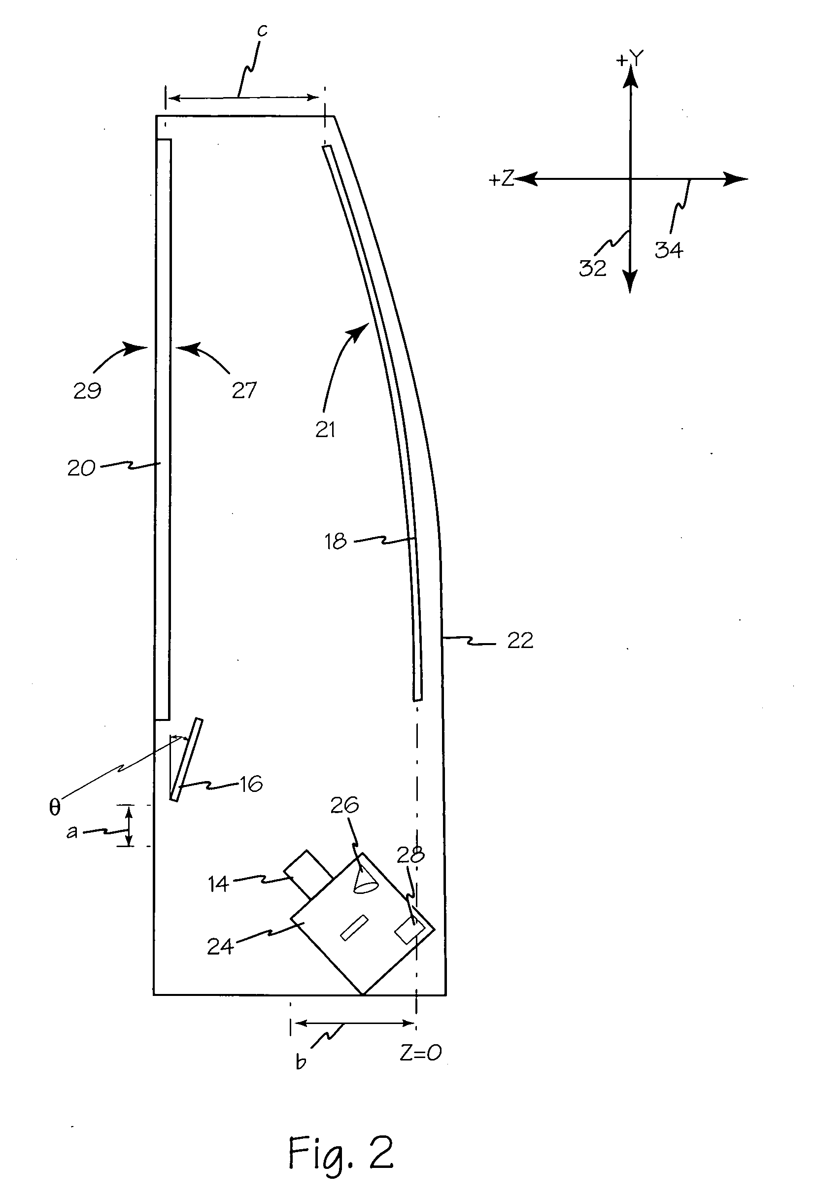
[0023] Referring to FIGS. 1 and 2 rear projection display 10 is illustrated according to the present disclosure. Rear projection monitor 10 includes projector 12, projection optics 14, first mirror 16, complex mirror 18, and screen 20. Rear projection monitor 10 may be of the thin type in which depth 23 is less than twelve inches. X axis 30, Y axis 32, and Z axis 34 are illustrated for reference purposes.

[0024] Projection optics 14, first mirror 16, complex mirror 18, and screen 20 are positioned such that they are symmetrical with respect to Y-Z plane 40. Y-Z plane 40 is perpendicular to screen 20 and bisects the screen along the screen's vertical centerline 20A.

[0025] Projector 12 is a micro display based projector containing an imager 24, light source 26, and electronics 28. Imager 24 may be any suitable device or combination of devices such as liquid crystal on silicon (LCoS), a digital micro mirror devices (DMD) imager, or the like using one or more such imaging devices. For ...


PUM


Abstract

A rear projection display according to the present disclosure includes a complex mirror as an optical element to simplify the optical design. The mirror may be symmetrical about at least one axis to require optimization of only half the optical system. The mirror may also provide a geometrically distorted image that may be corrected in software of the image generator. This display uses a mathematical formulation which inherently creates a surface which is symmetric about one linear axis but free form in an orthogonal axis.

Description

FIELD OF THE INVENTIONS [0001] The inventions described below relate the field of optics and more specifically to optical systems and software for projection video displays. BACKGROUND OF THE INVENTIONS [0002] Big screen micro display based rear projection imaging systems, such as televisions and monitors are becoming increasingly popular with consumers. This is due to their combination of low weight, high picture quality, price, and reliability over comparable large display technologies such as cathode ray tube (CRT) based rear projection imaging systems, plasma displays, and direct view liquid crystal displays (LCD). [0003] Micro display based rear projection imaging systems generally operate by shining a light on or through single or multiple micro displays (also known as imagers or light-valves) where an image is displayed. Micro display imagers, such as digital micro mirror devices (DMD) imagers, liquid crystal on silicon (LCoS) imagers, and LCD imagers, range from one half to ...

Claims


Application Information

Patent Timeline
IPC IPC(8): G03B21/28
CPCG03B21/10G03B21/28H04N9/3197H04N9/3185H04N9/3141
Inventor MCDOWALL, IAN
Owner FAKESPACE LABS
Why Eureka
Try Eureka