Video signal processing method, video signal processing apparatus, display apparatus
Inactive Publication Date: 2008-07-17
HITACHI LTD
View PDF3 Cites 9 Cited by
Summary
Abstract
Description
Claims
Application Information
AI Technical Summary
This helps you quickly interpret patents by identifying the three key elements:
Problems solved by technology
Method used
Benefits of technology
Benefits of technology
[0006]The present invention, accomplished by taking the drawback mentioned above into the consideration thereof, achieves a video display of high picture quality.
[0008]With such the structures mentioned above, it is possible to achieve the video display of high picture quality, while achieving or satisfying the both, i.e., reducing the dynamic false contour and preventing the omission of the light-ON information within the sub-field.
[0009]Thus, according to the present invention, it is possible to accomplish the video display of high picture quality.
Problems solved by technology
With the conventional correcting method with using the motion vector therein, since omission is generated of the light-ON information within the sub-field after the correction, it is impossible to achieve both, i.e., reducing the dynamic false contour and preventing the omission of the light-ON information within the sub-field, and therefore, there is a drawback that it is difficult to obtain a video display with high picture quality.
Method used
Image
Click on the blue label to locate the original text in one second.
Reading with bidirectional positioning of images and text.
Examples
embodiment 1
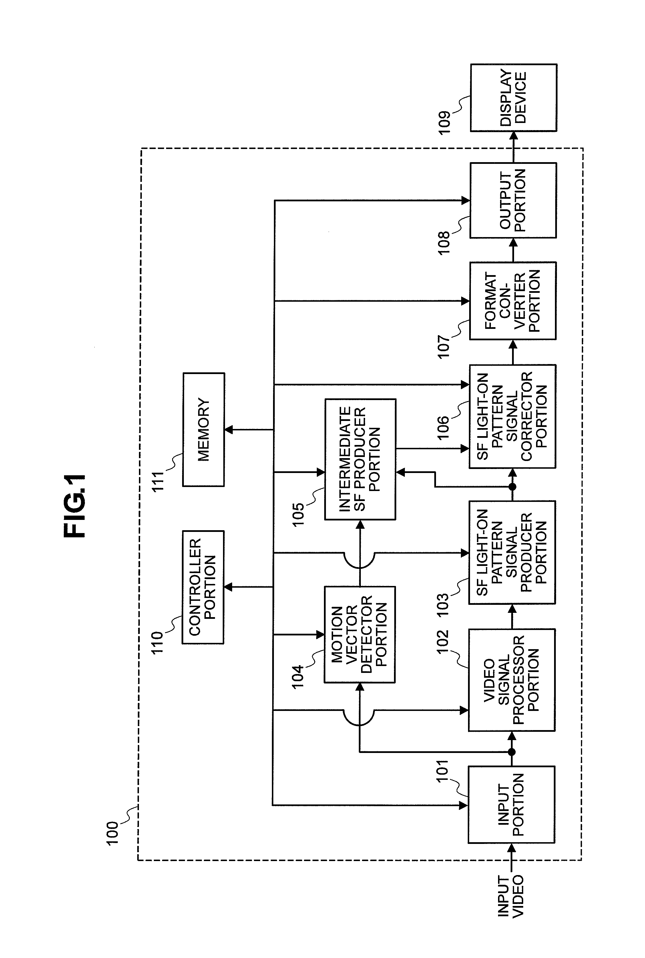
[0032]FIG. 1 shows an example of the structures of a video signal processing apparatus 100, according to the present invention. The video signal processing apparatus 100 shown in FIG. 1 is constructed with constituent elements, each conducting the following operations.
[0033]In the video signal processing apparatus 100, first of all, video inputted into an input portion 101 is transferred into a video signal processor portion 102, a motion vector detector portion 104, and an intermediate sub-field frame producer portion 105 (hereinafter, being described, an “intermediate SF frame producer portion”105). The video signal processor portion 102 conducts signal processing, such as, a gain adjustment or control and the reverse gamma (“γ”) correction, etc., depending a pixel value of the input video, so as to brining the color expression, brightness gradation and soon, into appropriate conditions thereof, when projecting the video on a display device 109. A sub-field light-ON pattern signal...
embodiment 2
[0104]FIG. 14 shows an example of the display apparatus, applying therein the video signal processing apparatus or the video signal processing method according to the embodiment mentioned above, as a second embodiment. In the embodiment of this FIG. 14, the display device 1400 is that using the sub-field light-ON pattern information, for example, such as, a plasma television apparatus or the like, enabling to conduct the gradation expression of brightness of the pixel, with using the sub-field light-ON pattern information, for example.
[0105]In the present embodiment, the display device 1400 is constructed with an input portion 1401, for controlling the operation of inputting the video contents, such as, through download of the video contents existing on the Internet, or the operation of outputting the video contents recorded by the plasma television apparatus into an outside thereof, a video contents storage portion 1404, for storing the video contents recorded therein, a recording / ...
embodiment 3
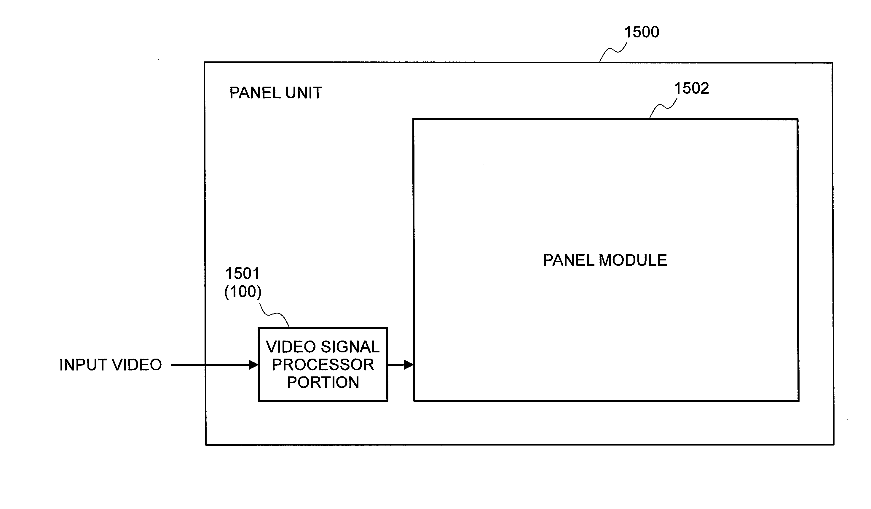
[0108]FIG. 15 shows an example of a panel unit with using the video signal processing apparatus and the video signal processing method according to the present embodiment, as a third embodiment of the present invention. Herein, as an example of the panel unit according to the present embodiment maybe, such as, a plasma panel including the video signal processing function within the plasma television apparatus, etc.
[0109]The panel unit 1500 installs a panel module 1502, and also a video signal processor device, for example, in the form of the video signal processor portion 1501. Herein, the video signal processor portion 1501 according to the present embodiment may be, such as, the display device 1400 installing the video signal processing apparatus 100 according to the embodiment 1, into the display device 1400, for example. Also, as the panel module 1502 may comprises a plural number of light-emitting elements and a light-On controller portion or a light-ON driver portion for those...
PUM
Abstract
For achieving a video display of high picture quality, a video signalprocessing method comprises the following steps of: a step for produce a sub-field light-ON pattern signal for controlling light-ON or -OFF at a pixel, during said plural number of sub-field periods, depending a pixel value of the pixel in the input video; and a signal correcting step for correcting said sub-field light-ON pattern signal, with using a motion vector obtained through a motion vector search, which is conducted on a first frame in said input video and a second frame, time-sequentially prior to said first frame, wherein said sub-field light-ON pattern signal has light-ON pattern signal for each pixel during each of the sub-field periods between said second frame and said first frame, and said signal correcting step determines the light-ON pattern information of one pixel during one sub-field period, with using a motion vector passing said one pixel within said sub-field among said motion vectors, while determining light-ON pattern information during said one sub-field of said one pixel when there is no motion vector passing through said one pixel, whereby producing a new sub-field light-ON pattern signal having the light-ON pattern information newly determined.
Description
BACKGROUND OF THE INVENTION[0001](1) Field of the Invention[0002]The present invention relates to a technology for reducing a dynamic false contour (or, a moving picture pseudo-outline)[0003](2) Description of the Related Art[0004]As the technology for reducing the dynamic false contour is already known a technology, for building up a sub-field in a moving direction of pixels, by referring to a motion vector of the pixels, thereby correcting it, as is disclosed, for example, in Japanese Patent Laying-Open No. 2000-163004 (2000), etc.SUMMARY OF THE INVENTION[0005]With the conventional correcting method with using the motion vector therein, since omission is generated of the light-ON information within the sub-field after the correction, it is impossible to achieve both, i.e., reducing the dynamic false contour and preventing the omission of the light-ON information within the sub-field, and therefore, there is a drawback that it is difficult to obtain a video display with high pictur...
Claims
Application Information
Patent Timeline
Application Date:The date an application was filed.
Publication Date:The date a patent or application was officially published.
First Publication Date:The earliest publication date of a patent with the same application number.
Issue Date:Publication date of the patent grant document.
PCT Entry Date:The Entry date of PCT National Phase.
Estimated Expiry Date:The statutory expiry date of a patent right according to the Patent Law, and it is the longest term of protection that the patent right can achieve without the termination of the patent right due to other reasons(Term extension factor has been taken into account ).
Invalid Date:Actual expiry date is based on effective date or publication date of legal transaction data of invalid patent.

