Light guide member, planar light source device using the light guide member, and display apparatus

A technology of light guide components and planar light sources, which is applied in the direction of optical components, light guides, lighting devices, etc., can solve the problems of increased backlight thickness, and achieve the effects of preventing obvious gaps, promoting uniformity, and high image quality

Inactive Publication Date: 2010-12-15
SHOWA DENKO KK
View PDF1 Cites 5 Cited by
  • Summary
  • Abstract
  • Description
  • Claims
  • Application Information

AI Technical Summary

Problems solved by technology

However, this method increases the thickness of the backlight and is not preferred for flat panel displays

Method used


Image

  • Light guide member, planar light source device using the light guide member, and display apparatus
  • Light guide member, planar light source device using the light guide member, and display apparatus
  • Light guide member, planar light source device using the light guide member, and display apparatus

Examples


Embodiment Construction

[0073] Hereinafter, a light guide member, a planar light source device using the same, and a display device relating to the present invention will be described in detail with reference to the accompanying drawings. The present invention is not limited to the following examples.

[0074] In the description of the embodiments of the present invention, for the convenience of explanation, "upward" refers to the direction from the light source (solid-state light emitting device) to the light guide element.

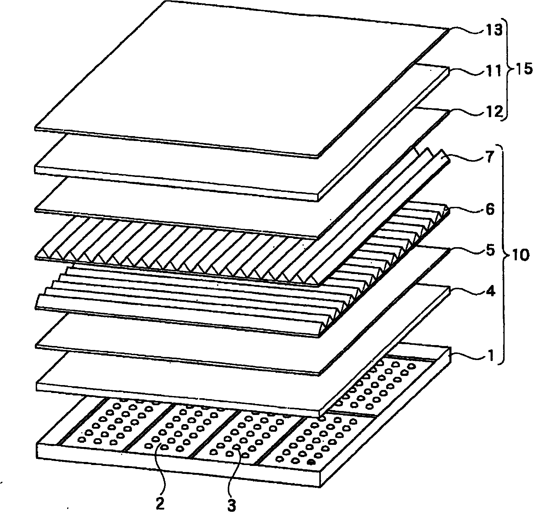
[0075] It is effective to employ a light guide member to sufficiently realize uniformity of luminance and chromaticity and to prevent increase in thickness of a planar light source device for a so-called direct-illumination type backlight. Since the solid state light emitting device is mounted upward for a direct lit backlight, diffuse and evenly spread light is preferred in the light guide element.

[0076] figure 1 is a view for showing the entire structure of an example o...


PUM

PropertyMeasurementUnit
thicknessaaaaaaaaaa

Abstract

A light guide member in which a light that has entered one major face from an illuminant is emitted from the other major face, is characterized by comprising: a cut portion provided with a specified face inclined toward the other face at a section of one major face that faces the illuminant, and a reflecting portion, which reflects a light emitted from the illuminant, on the inclined face.

Description

[0001] Cross References to Related Applications [0002] This application is filed under 35 U.S.C § 111(a) and requires provisional application 60 / 735,872 filed on November 14, 2005 under 35 U.S.C § 111(b) under 35 U.S.C § 119(e)(1), Priority of 60 / 752,892, filed December 23, 2005, and 60 / 797,775, filed May 5, 2006. technical field [0003] The present invention relates to a light guide member (plate) used in the case where a light source such as a light emitting diode is used as a light source for a liquid crystal backlight, a planar light source device using the light guide member (plate), and a display device. Background technique [0004] Generally, the mainstream of backlight light sources for liquid crystal displays is a so-called edge-light type in which cold cathode tubes are provided on the edge surface of a chassis (see Patent Document 1, for example). [0005] Figure 14 An edge-light type conventional backlight light source using cold cathode tubes is shown. ...

Claims


Application Information

Patent Timeline
Patent Type & Authority Applications(China)
IPC IPC(8): F21V8/00F21V13/00G02F1/13357
Inventor 五味秀二篠崎研二内条秀一渡边岳男
Owner SHOWA DENKO KK
Why Eureka
Try Eureka